## Diagram: Grid-Based Logic Puzzle State
### Overview
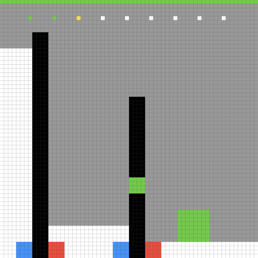
The image is a 2D, grid-based representation of a logic puzzle or level design, rendered in a pixel-art style. The scene is set against a white background with a gray grid overlay. The composition features a sequence of colored markers at the top, two vertical structures (pillars) with distinct base markers, and a standalone green block on the bottom right. There is no textual information present in the image.
### Components/Axes
The image is constructed on a uniform grid. The components are positioned as follows:
* **Top Row (Status/Sequence Bar):** A horizontal row of 10 colored squares positioned near the top of the gray background area.
* **Vertical Pillars:** Two distinct vertical structures composed of black pixels.
* **Left Pillar:** A tall, solid black column.
* **Right Pillar:** A shorter black column featuring a green segment in the middle.
* **Base Markers:** Both pillars are flanked at their base by colored squares.
* **Ground Object:** A green square block located on the bottom right of the grid.
### Detailed Analysis
#### 1. Top Row Sequence
Located at the top of the gray area, there is a sequence of 10 squares. From left to right, the colors are:
1. Green
2. Green
3. Yellow
4. White
5. White
6. White
7. White
8. White
9. White
10. White
#### 2. Vertical Pillars
* **Left Pillar:** A tall, solid black vertical bar. It spans from the bottom white floor area up into the gray background area. At its base, it is flanked by a **Blue square** on the left and a **Red square** on the right.
* **Right Pillar:** A shorter black vertical bar. It also spans from the bottom white floor area into the gray background. It contains a **Green square** segment embedded in the middle of the black column. At its base, it is also flanked by a **Blue square** on the left and a **Red square** on the right.
#### 3. Ground Object
* **Green Block:** Located in the bottom-right quadrant of the image, sitting on the white floor area. It appears to be a square block (approximately 4x4 grid units in size).
### Key Observations
* **Symmetry:** The base markers (Blue/Red) are identical for both pillars, suggesting a consistent control or interaction mechanism (e.g., "Blue" and "Red" switches or polarity).
* **Asymmetry:** Despite the identical bases, the pillars themselves are different. The left pillar is taller and solid black, while the right pillar is shorter and contains a green segment.
* **Color Coding:** The colors used (Green, Yellow, Blue, Red, White) are distinct and likely represent specific game mechanics or object types. The "Green" color appears in three contexts: the top sequence, the pillar segment, and the ground block, suggesting a thematic link between these elements.
* **Sequence:** The top row of squares acts as a header or a sequence indicator, with the first three squares (Green, Green, Yellow) being the only non-white elements.
### Interpretation
This image represents a state in a grid-based logic puzzle game. The visual language suggests a system where:
* **The Pillars** likely act as obstacles or interactive elements that can be manipulated or traversed.
* **The Base Markers (Blue/Red)** suggest a binary interaction system, perhaps indicating that the pillars can be toggled, moved, or activated using blue or red inputs.
* **The Green Segment** in the right pillar and the **Green Block** on the floor suggest that the right pillar may be related to the green block—perhaps the pillar is a receptacle for the block, or the block is a key to activating the pillar.
* **The Top Sequence** likely represents a "level goal" or a "code" that the player must solve. The presence of "Green, Green, Yellow" followed by seven "White" squares implies a sequence of actions or a state-matching requirement that the player must fulfill to complete the level.
The lack of text confirms this is a pure logic/spatial puzzle where the rules are communicated entirely through color and geometry.