## Block Diagram: Programmable Logic Array with Voltage-Controlled Switches
### Overview
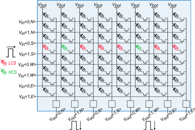
The diagram depicts a structured array of voltage-controlled logic switches organized in a grid format. It shows input voltage conditions (V_in) mapped to output voltage states (V_out) through a series of interconnected components. The system uses color-coded symbols (red for LCS, green for HCS) to indicate operational states or control conditions.
### Components/Axes
- **Vertical Input Axis (Left Side):**
- Labels: V_in<0,N>, V_in<1,N>, V_in<0,S>, V_in<1,S>, V_in<0,W>, V_in<1,W>, V_in<0,E>, V_in<1,E>
- Symbols: Red (LCS) and green (HCS) switches/icons
- Flow direction: Input signals enter from the left
- **Horizontal Output Axis (Bottom):**
- Labels: V_out<0,N>, V_out<1,N>, V_out<0,S>, V_out<1,S>, V_out<0,W>, V_out<1,W>, V_out<0,E>, V_out<1,E>
- Flow direction: Output signals exit downward
- **Grid Structure:**
- Columns labeled V_bot (repeated 8 times)
- Each column contains 8 identical switch-like components
- Components arranged in 8 rows corresponding to input conditions
- **Legend (Left Side):**
- Red symbol: LCS (Logic Control Switch)
- Green symbol: HCS (Hybrid Control Switch)
### Detailed Analysis
1. **Input-Output Mapping:**
- Each input condition (e.g., V_in<0,N>) connects to a corresponding output (V_out<0,N>)
- Inputs are categorized by directional subscripts (N, S, W, E) and binary states (0,1)
2. **Switch Component Behavior:**
- All switches share identical structure:
- Top: Voltage source (V_bot)
- Middle: Controlled by input conditions
- Bottom: Connected to output nodes
- Red (LCS) and green (HCS) symbols appear in specific input-output pairs:
- Red (LCS): V_in<0,S>, V_in<1,S>, V_in<0,W>, V_in<1,W>, V_in<0,E>, V_in<1,E>
- Green (HCS): V_in<0,S>, V_in<1,S>, V_in<0,W>, V_in<1,W>, V_in<0,E>, V_in<1,E>
3. **Control Logic:**
- The grid suggests a matrix of configurable logic gates
- V_bot appears to be a common control voltage for all switches
- Input conditions determine which switches activate (red/green states)
### Key Observations
1. **Symmetry in Control:**
- All directional subscripts (N,S,W,E) appear equally in both input and output
- Binary states (0,1) are consistently paired across the grid
2. **Color Distribution:**
- Red (LCS) and green (HCS) symbols appear in identical positions across all columns
- No variation in symbol placement between columns
3. **Flow Consistency:**
- All input signals follow identical left-to-right then downward flow
- Outputs maintain uniform downward trajectory
### Interpretation
This diagram represents a configurable logic array where:
1. **Directional Control:** The N/S/W/E subscripts suggest spatial orientation control, possibly for a multi-axis system
2. **Binary State Management:** The 0/1 states indicate digital logic control
3. **Hybrid Operation:** The coexistence of LCS and HCS suggests a system combining pure logic with hybrid control mechanisms
4. **Modular Design:** The repeated V_bot columns imply a scalable architecture where additional control voltages can be added
The system appears designed for complex pattern recognition or spatial data processing, where input conditions (V_in) determine output states (V_out) through programmable logic paths. The consistent symbol placement across columns suggests standardized control protocols for each directional quadrant.