## Diagram: Parallel Processing Pipeline
### Overview
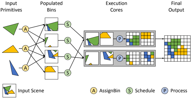
The image illustrates a parallel processing pipeline for rendering a scene composed of geometric primitives. The pipeline consists of stages for assigning primitives to bins, scheduling the bins for execution, processing the bins in parallel on execution cores, and generating the final output.
### Components/Axes
* **Header:** Contains the stage names: "Input Primitives", "Populated Bins", "Execution Cores", and "Final Output".
* **Input Primitives:** Shows three geometric shapes: a green triangle, a yellow trapezoid, and a blue triangle.
* **AssignBin (A):** A column of four yellow circles labeled "A", representing the assignment of input primitives to bins. Each primitive is assigned to multiple bins.
* **Populated Bins:** Four square bins, each containing a subset of the input primitives. The first bin contains the green triangle, the second bin contains the green triangle and a small portion of the yellow trapezoid, the third bin contains the blue triangle and a small portion of the yellow trapezoid, and the fourth bin contains the yellow trapezoid.
* **Schedule (S):** A column of four green circles labeled "S", representing the scheduling of the populated bins for execution.
* **Execution Cores:** Two parallel processing units. Each unit contains two bins and a processing stage. The first unit contains the first and second populated bins, and the second unit contains the third and fourth populated bins.
* **Process (P):** Two blue circles labeled "P", representing the processing of the bins within each execution core.
* **Final Output:** A grid representing the final rendered image, composed of colored cells corresponding to the input primitives.
* **Legend (Bottom-Left):** A square containing a combination of the green triangle and yellow trapezoid, labeled "Input Scene".
* **Legend (Bottom):**
* Yellow circle labeled "A AssignBin"
* Green circle labeled "S Schedule"
* Blue circle labeled "P Process"
### Detailed Analysis
* **Input Primitives:** The input consists of three distinct geometric shapes, each with a different color.
* **AssignBin:** Each input primitive is assigned to multiple bins. The green triangle is assigned to the first two bins, the yellow trapezoid is assigned to the second, third, and fourth bins, and the blue triangle is assigned to the third bin.
* **Populated Bins:** The bins contain different combinations of the input primitives.
* **Schedule:** Each bin is scheduled for execution.
* **Execution Cores:** The bins are processed in parallel on two execution cores. Each core processes two bins.
* **Process:** Within each core, the bins are processed to generate a partial output.
* **Final Output:** The partial outputs from the execution cores are combined to generate the final rendered image. The final output is a grid where the cells are colored according to the primitives that cover them. The colors are green, yellow, and blue, corresponding to the input primitives.
### Key Observations
* The pipeline demonstrates a parallel processing approach to rendering.
* The input primitives are distributed across multiple bins.
* The bins are processed in parallel on multiple execution cores.
* The final output is a combination of the partial outputs from the execution cores.
### Interpretation
The diagram illustrates a common technique in parallel rendering where the scene is divided into smaller units (bins) that can be processed independently. This allows for efficient utilization of multiple processing cores, leading to faster rendering times. The "AssignBin" and "Schedule" stages are crucial for distributing the workload and ensuring that the cores are kept busy. The final output represents the composited result of the parallel processing, demonstrating how the individual contributions of each core combine to form the complete image. The diagram highlights the flow of data and the transformations that occur at each stage of the pipeline.