## Flowchart Diagram: System Process Flow
### Overview
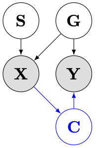
The image depicts a flowchart with five nodes labeled **S**, **G**, **X**, **Y**, and **C**, connected by directional arrows. The diagram uses a minimalist design with black arrows (except one blue arrow) on a white background. Nodes are represented as circles, with **S** and **G** at the top, **X** and **Y** in the middle, and **C** at the bottom.
### Components/Axes
- **Nodes**:
- **S** (Top-left)
- **G** (Top-right)
- **X** (Center-left, gray-shaded)
- **Y** (Center-right, gray-shaded)
- **C** (Bottom, blue-shaded)
- **Arrows**:
- Black arrows connect **S → X**, **G → X**, **X → Y**, and **Y → C**.
- A single **blue arrow** connects **Y → C**, diverging from the black arrows.
- **No axes, legends, or numerical scales** are present.
### Detailed Analysis
- **Flow Direction**:
- **S** and **G** both feed into **X**.
- **X** directs output to **Y**.
- **Y** directs output to **C** via a **blue arrow**, while a black arrow also points from **Y → C** (redundant or parallel path?).
- **Color Coding**:
- **Gray shading** for **X** and **Y** may indicate intermediate processing stages.
- **Blue shading** for **C** could signify a final output or critical endpoint.
- The **blue arrow** from **Y → C** is unique, suggesting a distinct relationship (e.g., feedback, exception, or priority path).
### Key Observations
1. **Redundant Path**: The presence of both black and blue arrows from **Y → C** implies ambiguity in the process flow. This could represent:
- A primary path (blue) and a secondary path (black).
- A feedback loop (blue) alongside a linear progression (black).
2. **Hierarchical Structure**: The diagram suggests a top-down flow, with **S** and **G** as inputs, **X** and **Y** as processing stages, and **C** as the output.
3. **No Data Labels**: No numerical values, percentages, or textual descriptions are provided to quantify relationships.
### Interpretation
- **Process Flow**: The diagram likely represents a system where inputs (**S**, **G**) converge at **X**, which processes data to **Y**, ultimately producing **C**. The blue arrow may highlight a critical or alternative route to **C**.
- **Ambiguity in Flow**: The dual arrows from **Y → C** require clarification. This could indicate:
- A conditional branch (e.g., success vs. failure paths).
- A feedback mechanism where **C** influences **Y**.
- **Design Intent**: The use of color (gray for intermediates, blue for the final node/arrow) emphasizes the endpoint **C** and its unique connection to **Y**.
### Conclusion
This flowchart outlines a conceptual process flow with inputs (**S**, **G**), intermediate stages (**X**, **Y**), and an output (**C**). The blue arrow introduces ambiguity, suggesting a need for further clarification on its purpose (e.g., feedback, exception handling). Without additional context or data, the diagram serves as a high-level schematic rather than a quantitative model.