## Diagram: Physics Problem Illustration - Projectile Motion Trajectories
### Overview
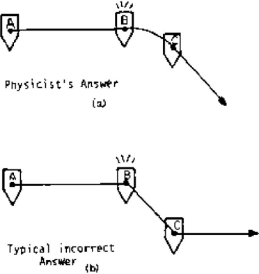
The image contains two black-and-white schematic diagrams, labeled (a) and (b), stacked vertically. They illustrate two different conceptual answers to a physics problem involving the motion of an object from point A to point C, passing through point B. The diagrams contrast a correct ("Physicist's") solution with a common incorrect one.
### Components/Axes
* **Diagram (a) - Top:**
* **Label:** "Physicist's Answer" centered below the diagram, with "(a)" beneath it.
* **Components:** Three points labeled **A**, **B**, and **C**, each marked with a downward-pointing triangle.
* **Path:** A straight horizontal line connects **A** to **B**. From **B**, a smooth, downward-curving line (parabolic arc) connects to **C**. An arrowhead at the end of the curve points downward and to the right.
* **Symbol:** A starburst or explosion symbol is drawn above point **B**.
* **Diagram (b) - Bottom:**
* **Label:** "Typical incorrect Answer" centered below the diagram, with "(b)" beneath it.
* **Components:** Identical setup to (a) with points **A**, **B**, and **C** marked by triangles.
* **Path:** A straight horizontal line connects **A** to **B**. From **B**, a straight diagonal line connects to **C**. An arrowhead at the end of this line points horizontally to the right.
* **Symbol:** An identical starburst symbol is drawn above point **B**.
### Detailed Analysis
The diagrams present a visual comparison of two conceptual models for the same physical scenario.
* **Common Elements (Both Diagrams):**
* **Initial Motion:** The object travels in a straight, horizontal line from point **A** to point **B**.
* **Event at B:** The starburst symbol at **B** suggests a critical event occurs there, such as an explosion, a release, or a change in the forces acting on the object.
* **Final Destination:** The object's path ends at point **C**.
* **Critical Difference (Path from B to C):**
* **In Diagram (a) - "Physicist's Answer":** The path from **B** to **C** is a **downward-curving parabola**. This trajectory is characteristic of **projectile motion** under the influence of gravity, where the object has an initial horizontal velocity component from its motion from A to B, but is also subject to constant downward acceleration.
* **In Diagram (b) - "Typical incorrect Answer":** The path from **B** to **C** is a **straight diagonal line**. This represents a common intuitive but incorrect model where the object is assumed to travel in a straight line from its new starting point **B** to its destination **C**, ignoring the continuous effect of gravity which would curve its path.
### Key Observations
1. **Spatial Layout:** The two diagrams are presented for direct vertical comparison, emphasizing the contrast in the **B-to-C** path.
2. **Symbolic Consistency:** The identical starburst at **B** in both diagrams confirms the event at that point is the same; only the subsequent motion model differs.
3. **Directional Arrows:** The arrowhead in (a) points along the tangent of the curve (downward-right), consistent with velocity in projectile motion. The arrowhead in (b) points purely horizontally, which is inconsistent with the diagonal straight-line path shown, suggesting a possible additional error in the diagram's own logic.
4. **Labeling:** The labels explicitly frame the comparison as between a correct scientific understanding and a widespread misconception.
### Interpretation
This image is a pedagogical illustration designed to highlight a specific conceptual error in physics reasoning.
* **What it Demonstrates:** It contrasts the correct application of kinematic principles (accounting for gravity's continuous acceleration) with an intuitive but flawed "straight-line" or "impulse" model of motion. The "Physicist's Answer" correctly shows that an object with horizontal velocity, once free of its initial constraint (at point B), will follow a parabolic path due to gravity. The "Typical incorrect Answer" shows the common mistake of assuming the object instantly changes to a new straight-line trajectory toward the target.
* **Relationship Between Elements:** The horizontal line **A-B** sets up an initial condition of horizontal motion. The event at **B** (explosion/release) changes the forces, and the subsequent path **B-C** reveals the underlying physical model being used. The diagrams are a visual "spot the difference" exercise for students.
* **Notable Anomaly:** The arrowhead in diagram (b) is horizontally oriented, while the line it terminates is diagonal. This internal inconsistency might be an intentional part of the illustration to further emphasize the incorrectness of the model, or a drafting error.
* **Underlying Message:** The image teaches that correct physical prediction requires applying fundamental laws (like F=ma and the independence of motion components) continuously, not just at discrete points. It warns against relying on geometric intuition for dynamic problems.