\n
## Digital Logic Diagram: Combinational Logic Circuit
### Overview
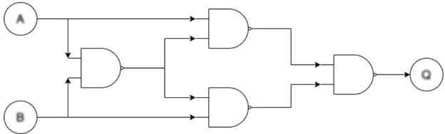
The image depicts a digital logic circuit diagram composed of AND and OR gates. The circuit takes two inputs, labeled 'A' and 'B', and produces a single output, labeled 'Q'. The diagram illustrates the interconnection of these logic gates to perform a specific boolean function.
### Components/Axes
The diagram consists of the following components:
* **Inputs:** A and B, represented by circles.
* **Logic Gates:**
* Two AND gates.
* Two OR gates.
* One final AND gate.
* **Output:** Q, represented by a circle.
* **Lines:** Representing the flow of signals between components.
### Detailed Analysis or Content Details
The circuit can be described as follows:
1. Input A is fed directly into one OR gate and also into one AND gate.
2. Input B is fed directly into one OR gate and also into the same AND gate as input A.
3. The output of the AND gate (A AND B) is fed into the final AND gate.
4. The output of the first OR gate (A OR B) is fed into the final AND gate.
5. The output of the second OR gate (A OR B) is also fed into the final AND gate.
6. The output of the final AND gate is the output Q.
Therefore, the output Q can be expressed as:
Q = (A AND B) AND ((A OR B) OR (A OR B))
Simplifying the expression:
Q = (A AND B) AND (A OR B)
This is equivalent to the AND operation.
### Key Observations
The circuit effectively implements an AND gate. The intermediate OR gates and the final AND gate are redundant, as the output is solely determined by the AND operation of inputs A and B.
### Interpretation
The diagram demonstrates a potentially inefficient implementation of a simple AND gate. While functionally correct, the circuit utilizes more gates than necessary. This could be a pedagogical example illustrating the equivalence of different logic gate configurations or a demonstration of how logic simplification can lead to more efficient circuit designs. The redundancy suggests a possible design flaw or a deliberate attempt to showcase the versatility of logic gate combinations. The circuit's behavior is entirely determined by the simultaneous truth of inputs A and B, mirroring the fundamental operation of an AND gate.