## Circuit Diagram
### Overview
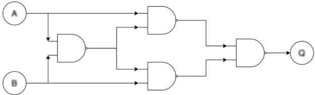
The image depicts a circuit diagram consisting of logic gates. The diagram includes two input signals, labeled A and B, and an output signal, labeled Q. The logic gates used are AND gates and OR gates.
### Components/Axes
- **Input Signals**: A and B
- **AND Gates**: Two AND gates are present in the circuit.
- **OR Gate**: One OR gate is present in the circuit.
- **Output Signal**: Q
### Detailed Analysis or ### Content Details
The circuit diagram shows the following connections:
- Input A is connected to the first AND gate and the second AND gate.
- Input B is connected to the first AND gate and the second AND gate.
- The output of the first AND gate is connected to the input of the OR gate.
- The output of the second AND gate is also connected to the input of the OR gate.
- The output of the OR gate is labeled as Q.
### Key Observations
- The circuit uses a combination of AND and OR gates to process the input signals A and B.
- The output signal Q is determined by the combination of the outputs from the AND gates and the OR gate.
- The circuit appears to be a basic logic circuit used for signal processing or decision-making.
### Interpretation
The circuit diagram represents a simple logic circuit that takes two input signals, A and B, and produces an output signal, Q. The output Q is determined by the logical operations performed by the AND and OR gates. The AND gates ensure that both input signals must be high for the output to be high, while the OR gate allows the output to be high if at least one of the input signals is high. This type of circuit is commonly used in digital electronics for various applications such as data processing, control systems, and signal processing.