## Diagram: Directed Graph with Malicious Node Indicator
### Overview
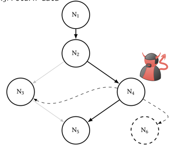
The image is a directed graph consisting of six nodes labeled $N_1$ through $N_6$. The diagram illustrates a flow of operations or data, with distinct visual styles (solid black, solid gray, and dashed lines) indicating different types of relationships or paths. A cartoon "devil" icon is positioned next to node $N_4$, suggesting that this specific node represents a malicious, compromised, or "bad" entity within the system architecture. The text "Return data" is partially visible in the top-left corner.
### Components/Axes
* **Nodes:** Six circular nodes labeled $N_1, N_2, N_3, N_4, N_5, N_6$.
* $N_1$: Top-center.
* $N_2$: Upper-middle.
* $N_3$: Middle-left.
* $N_4$: Middle-right.
* $N_5$: Bottom-center.
* $N_6$: Bottom-right (represented by a dashed circle).
* **Edges (Connections):**
* **Solid Black Lines:** Represent primary or active paths.
* **Solid Gray Lines:** Represent secondary or benign paths.
* **Dashed Black Lines:** Represent conditional, suspicious, or alternative paths.
* **Iconography:** A cartoon devil icon (red skin, horns, goatee) located to the top-right of node $N_4$.
* **Text:** "Return data" (partially visible, top-left).
### Detailed Analysis
The flow of the graph can be traced as follows:
1. **Root:** The process begins at **$N_1$** (top-center), which connects via a solid black line to **$N_2$** (upper-middle).
2. **Branching:** From **$N_2$**, the path splits:
* A solid gray line leads to **$N_3$** (middle-left).
* A solid black line leads to **$N_4$** (middle-right).
3. **The "Devil" Node ($N_4$):** This node acts as a central hub for three outgoing paths:
* A dashed black line leads back to **$N_3$**.
* A solid black line leads down to **$N_5$** (bottom-center).
* A dashed black line leads to **$N_6$** (bottom-right).
4. **Secondary Flow:** **$N_3$** connects to **$N_5$** via a solid gray line.
### Summary of Connections
| Source | Destination | Line Style |
| :--- | :--- | :--- |
| $N_1$ | $N_2$ | Solid Black |
| $N_2$ | $N_3$ | Solid Gray |
| $N_2$ | $N_4$ | Solid Black |
| $N_4$ | $N_3$ | Dashed Black |
| $N_4$ | $N_5$ | Solid Black |
| $N_4$ | $N_6$ | Dashed Black |
| $N_3$ | $N_5$ | Solid Gray |
### Key Observations
* **The "Devil" Indicator:** The placement of the devil icon specifically on $N_4$ is the most significant visual cue. It implies that $N_4$ is the source of malicious activity or a point of compromise.
* **Dashed vs. Solid:** The use of dashed lines originating from $N_4$ ($N_4 \rightarrow N_3$ and $N_4 \rightarrow N_6$) suggests that these paths are either unauthorized, conditional, or represent the "malicious" flow of data, contrasting with the solid lines which appear to be the "intended" or "benign" flow.
* **$N_6$ Distinction:** $N_6$ is the only node drawn with a dashed circle, suggesting it is a potential destination for exfiltrated data or a "sink" for the malicious activity originating from $N_4$.
* **Gray Path:** The path $N_2 \rightarrow N_3 \rightarrow N_5$ is entirely gray, suggesting this is the "clean" or "normal" path that the system is intended to follow.
### Interpretation
This diagram is likely a threat model or a security analysis visualization.
* **The "Return data" context:** The text at the top-left suggests the diagram describes a data exfiltration scenario.
* **The Attack Vector:** The system appears to be designed to flow from $N_1 \rightarrow N_2 \rightarrow N_3 \rightarrow N_5$. However, $N_4$ has been introduced (or compromised) as an intercept point.
* **Malicious Interception:** Data flowing from $N_2$ is diverted to $N_4$. From $N_4$, the attacker is potentially sending data back to $N_3$ (perhaps to maintain persistence or manipulate the "clean" path) and exfiltrating data to $N_6$ (the dashed sink).
* **Conclusion:** The diagram demonstrates how a malicious actor ($N_4$) can sit in the middle of a legitimate data flow, allowing them to siphon information to an external or unauthorized location ($N_6$) while potentially masking their presence by interacting with the legitimate nodes ($N_3$).