## Diagram: Equivalent Representations of a System
### Overview
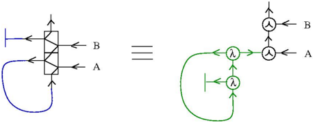
The image presents two equivalent representations of a system, likely related to control systems or signal processing. The left side shows a block diagram with a specific configuration, while the right side shows an equivalent representation using a different set of components. The two sides are linked by an "equals" sign, indicating equivalence.
### Components/Axes
* **Left Side:**
* A rectangular block with internal diagonal lines.
* Input arrows pointing into the block from the left and bottom.
* Output arrows pointing out of the block to the top and right, labeled "B" and "A" respectively.
* A feedback loop in blue connecting the output "A" to the bottom input.
* A short horizontal line segment on the left, connected to the input arrow.
* **Right Side:**
* Two circular nodes, each containing the symbol "λ" (lambda), colored green.
* Two circular nodes, each containing the symbol "∧" (logical AND), colored black.
* Input arrows pointing into the top "∧" node and the rightmost "∧" node, labeled "B" and "A" respectively.
* A feedback loop in green connecting the bottom "λ" node to the leftmost "λ" node.
* Arrows indicating the flow of signals between the nodes.
* A short horizontal line segment on the left, connected to the green feedback loop.
* **Central Connector:**
* An equals sign "===" between the two diagrams, indicating equivalence.
### Detailed Analysis or Content Details
**Left Side (Block Diagram):**
* The rectangular block has two inputs and two outputs.
* The input from the left goes into the top of the block.
* The input from the bottom is the feedback from output A.
* The output at the top is labeled B.
* The output on the right is labeled A.
* The feedback loop connects output A to the bottom input of the block.
**Right Side (Equivalent Representation):**
* The top "∧" node has an input labeled "B".
* The rightmost "∧" node has an input labeled "A".
* The two "∧" nodes are connected by an arrow.
* The leftmost "λ" node is connected to the top "∧" node.
* The bottom "λ" node is connected to the rightmost "λ" node.
* The feedback loop connects the bottom "λ" node to the leftmost "λ" node.
### Key Observations
* The two diagrams represent the same system using different notations.
* The left side uses a block diagram approach, while the right side uses a node-based representation.
* The "λ" nodes likely represent some form of gain or scaling, while the "∧" nodes likely represent logical AND operations.
* The feedback loop is present in both diagrams, indicating a closed-loop system.
### Interpretation
The image demonstrates the equivalence between two different representations of a system. The block diagram on the left provides a high-level view of the system, while the node-based representation on the right provides a more detailed view of the internal components and their interactions. The use of "λ" and "∧" symbols suggests that the system may involve both linear and non-linear operations. The feedback loop indicates that the system is likely designed to regulate or control some variable. The equivalence of the two diagrams implies that they can be used interchangeably to analyze or design the system.