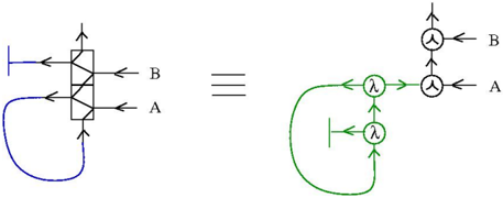
## Diagram: Equivalent System Representation
### Overview
The image depicts two equivalent system diagrams connected by a triple-bar equivalence symbol (≡). The left diagram uses a blue square with internal arrows, while the right diagram uses green circular nodes with lambda (λ) symbols. Both diagrams include labeled inputs/outputs (A, B) and directional flow indicators.
### Components/Axes
- **Left Diagram (Blue Square)**:
- Central square with diagonal internal arrows (no explicit labels).
- Arrows labeled **A** (input) and **B** (output) on the left and top sides, respectively.
- Feedback loop arrow at the bottom (no label).
- **Right Diagram (Green Nodes)**:
- Two green circular nodes labeled **λ** (lambda symbols).
- Arrows connecting nodes in a loop (clockwise).
- Arrows labeled **A** (input) and **B** (output) on the left and top sides, respectively.
- **Equivalence Symbol**:
- Triple-bar symbol (≡) between diagrams, indicating functional equivalence.
### Detailed Analysis
- **Left Diagram**:
- The square’s internal arrows suggest a bidirectional or cross-coupled process.
- Input **A** enters the system, processes through the square, and exits as output **B**.
- Feedback loop implies self-reinforcement or recycling of output.
- **Right Diagram**:
- Two lambda nodes form a closed loop, suggesting iterative or cyclical processing.
- Input **A** enters the loop, processes through both λ nodes, and exits as output **B**.
- Lambda symbols may represent parameters, feedback factors, or transformation steps.
### Key Observations
1. **Equivalence**: Both diagrams represent the same system behavior despite differing visual structures.
2. **Feedback Mechanisms**: Both systems incorporate feedback (left: explicit loop; right: implicit loop via λ nodes).
3. **Input/Output Symmetry**: Input **A** and output **B** are positioned identically in both diagrams.
### Interpretation
The diagram illustrates two equivalent representations of a dynamic system:
- The **left diagram** emphasizes structural simplicity (a single processing unit with feedback).
- The **right diagram** highlights modularity (two interconnected processing steps with cyclical behavior).
- The lambda (λ) symbols likely denote adjustable parameters or feedback coefficients, critical for system tuning.
- The equivalence (≡) implies that both models can be used interchangeably for analysis, depending on the required level of detail.
This representation is common in control systems, signal processing, or feedback loop analysis, where multiple equivalent models aid in optimization or fault diagnosis.