\n
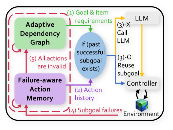
## Diagram: Adaptive Control Loop with LLM
### Overview
The image depicts a diagram of an adaptive control loop incorporating a Large Language Model (LLM). The system consists of several components: an Adaptive Dependency Graph, a Failure-aware Action Memory, an LLM, a Controller, and an Environment. Arrows indicate the flow of information and control between these components. The diagram is enclosed within a dashed red border, suggesting a closed-loop system.
### Components/Axes
The key components are:
* **Adaptive Dependency Graph:** A green rectangular block.
* **Failure-aware Action Memory:** A purple rectangular block.
* **LLM:** A light gray rectangular block.
* **Controller:** A blue rectangular block.
* **Environment:** A small cube-shaped icon with a textured surface.
* **Decision Node:** An oval shape labeled "If (past successful subgoal exists)".
The diagram also includes numbered labels indicating the flow of information:
1. Goal & item requirements
2. Action history
3. Call LLM / Reuse subgoal
4. Subgoal failures
5. All actions are invalid
### Detailed Analysis or Content Details
The diagram illustrates the following flow:
1. **Goal & item requirements** (labeled '1', green arrow) flow from the Adaptive Dependency Graph to the LLM.
2. **Action history** (labeled '2', purple arrow) flows from the Failure-aware Action Memory to the decision node "If (past successful subgoal exists)".
3. From the decision node, two paths emerge:
* If a past successful subgoal exists, a **Reuse subgoal** signal (labeled '3-O', yellow arrow) is sent to the Controller.
* If no past successful subgoal exists, a **Call LLM** signal (labeled '3-X', yellow arrow) is sent to the LLM.
4. **Subgoal failures** (labeled '4', red dashed arrow) flow from the Environment to the Failure-aware Action Memory.
5. **All actions are invalid** (labeled '5', red arrow) flow from the Failure-aware Action Memory to the Adaptive Dependency Graph.
The Controller interacts with the Environment, as indicated by the bidirectional arrow between them. The LLM also interacts with the Controller via the yellow arrows.
### Key Observations
* The system is designed to learn from past successes and failures. The Failure-aware Action Memory and the Adaptive Dependency Graph play crucial roles in this learning process.
* The LLM is used both to generate new subgoals (when no past successful subgoal exists) and to reuse existing subgoals (when a past successful subgoal exists).
* The red dashed border and the red arrows suggest a feedback loop for handling failures.
* The diagram emphasizes the adaptive nature of the control loop, as the system can adjust its behavior based on the environment and past experiences.
### Interpretation
This diagram represents a sophisticated control system that leverages the capabilities of an LLM to achieve goals in a dynamic environment. The system's ability to learn from failures and reuse successful subgoals suggests a high degree of efficiency and robustness. The Adaptive Dependency Graph likely represents the relationships between different tasks or subgoals, allowing the system to plan and execute complex actions. The Failure-aware Action Memory provides a mechanism for avoiding repeated mistakes and improving performance over time. The LLM acts as a central intelligence, capable of generating novel solutions when needed and leveraging existing knowledge when appropriate. The overall architecture suggests a system designed for autonomous operation in complex and uncertain environments. The use of numbered labels indicates a specific sequence of operations or a workflow within the system. The diagram is a high-level representation of the system's architecture and does not provide specific details about the implementation of each component.