## System Diagram: FPGA-Based Spiking Neural Network
### Overview
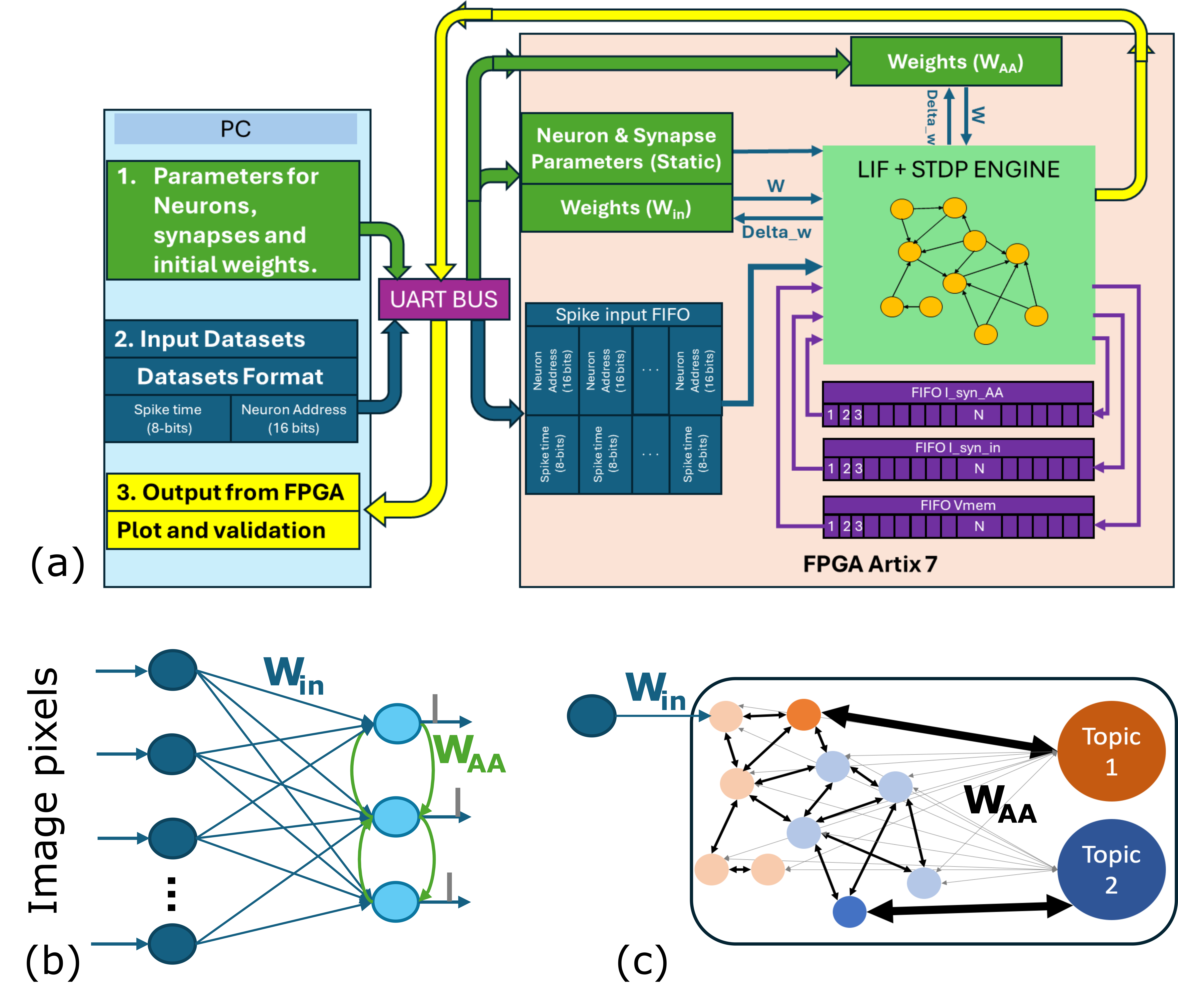
The image presents a system diagram of an FPGA-based spiking neural network (SNN) implementation. It illustrates the data flow and processing stages from the PC to the FPGA, including parameter loading, input data formatting, and output validation. The diagram also depicts the internal architecture of the FPGA, highlighting the LIF + STDP engine and memory structures.
### Components/Axes
* **PC (Top-Left)**: Represents the host computer responsible for configuring the network and providing input data.
* **1. Parameters for Neurons, synapses and initial weights**: Indicates the initial configuration data sent to the FPGA.
* **2. Input Datasets Datasets Format**: Specifies the format of the input spike data. Spike time (8-bits), Neuron Address (16 bits).
* **3. Output from FPGA Plot and validation**: Describes the output data used for validation.
* **UART BUS (Center-Left)**: The communication interface between the PC and the FPGA.
* **FPGA Artix 7 (Bottom-Right)**: The target hardware platform for the SNN implementation.
* **Neuron & Synapse Parameters (Static) (Top-Center)**: Stores static parameters of the neurons and synapses.
* **Weights (W<sub>in</sub>) (Center)**: Stores the input weights.
* **Weights (W<sub>AA</sub>) (Top-Right)**: Stores the recurrent weights.
* **LIF + STDP ENGINE (Center-Right)**: The core processing unit implementing the Leaky Integrate-and-Fire (LIF) neuron model and Spike-Timing-Dependent Plasticity (STDP) learning rule.
* **FIFO I\_syn\_AA (Center-Right)**: FIFO memory for recurrent synaptic inputs.
* "1 2 3 ... N" indicates the memory locations.
* **FIFO I\_syn\_in (Center-Right)**: FIFO memory for input synaptic inputs.
* "1 2 3 ... N" indicates the memory locations.
* **FIFO Vmem (Center-Right)**: FIFO memory for neuron membrane potentials.
* "1 2 3 ... N" indicates the memory locations.
* **(a) (Bottom-Left)**: Overall system architecture.
* **(b) (Bottom-Left)**: Network diagram showing input pixels connected to a recurrent layer.
* **Image pixels (Left)**: Input layer representing image pixel values.
* **W<sub>in</sub> (Top-Center)**: Input weights connecting image pixels to the recurrent layer.
* **W<sub>AA</sub> (Center)**: Recurrent weights within the recurrent layer.
* **(c) (Bottom-Right)**: Network diagram showing connections between neurons and topic outputs.
* **W<sub>in</sub> (Top-Left)**: Input weights.
* **W<sub>AA</sub> (Center)**: Recurrent weights.
* **Topic 1 (Top-Right)**: Output representing topic 1.
* **Topic 2 (Bottom-Right)**: Output representing topic 2.
### Detailed Analysis or ### Content Details
* **Data Flow**:
* Parameters for neurons, synapses, and initial weights are sent from the PC to the FPGA via the UART bus.
* Input datasets, formatted as spike time (8-bits) and neuron address (16 bits), are sent from the PC to the FPGA via the UART bus.
* Spike input data is stored in the Spike input FIFO.
* The LIF + STDP engine processes the spike data and updates the weights (W<sub>in</sub> and W<sub>AA</sub>).
* The updated weights (Delta\_w) are sent back to the Weights (W<sub>in</sub>) and Weights (W<sub>AA</sub>) blocks.
* Output data from the FPGA is sent back to the PC for plotting and validation.
* **Network Architecture**:
* The network consists of an input layer (image pixels) connected to a recurrent layer.
* The recurrent layer has recurrent connections (W<sub>AA</sub>).
* The recurrent layer is connected to topic outputs (Topic 1 and Topic 2).
### Key Observations
* The system uses an FPGA to implement a spiking neural network.
* The network uses LIF neurons and STDP learning.
* The system includes FIFO memories for storing spike data and membrane potentials.
* The network architecture includes an input layer, a recurrent layer, and topic outputs.
### Interpretation
The diagram illustrates a hardware implementation of a spiking neural network on an FPGA. The system is designed to process spike data and learn using STDP. The network architecture is suitable for tasks such as image recognition and topic modeling. The use of an FPGA allows for parallel processing and real-time performance. The diagram provides a high-level overview of the system and its components.