## Diagram: Neuromorphic Computing System Architecture
### Overview
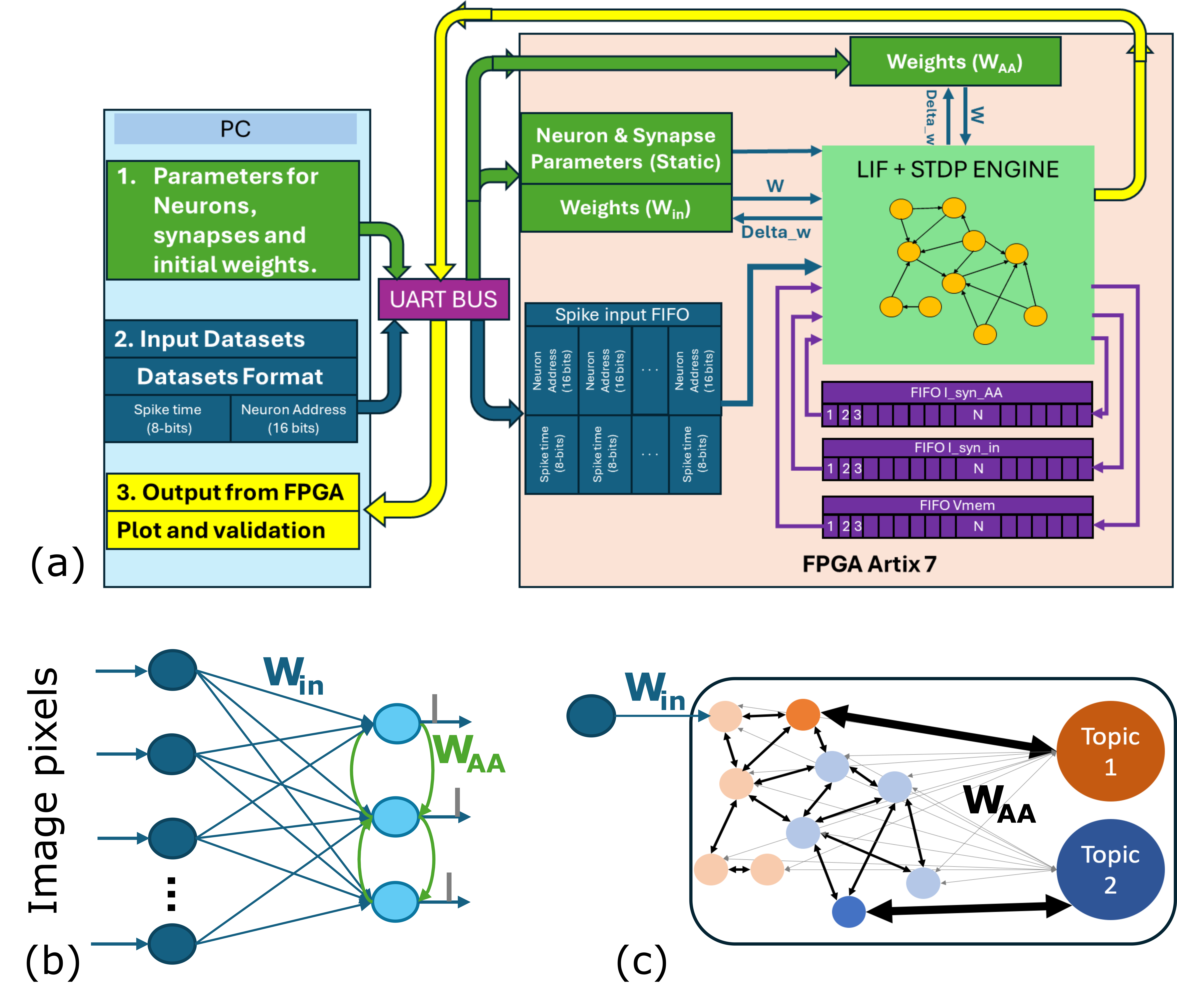
This diagram illustrates the architecture of a neuromorphic computing system, specifically focusing on the interaction between a host PC, an FPGA (Artix7), and the LIF + STDP engine. It details the data flow for parameter setting, input data transfer, and output retrieval. The diagram is divided into three main sections: (a) System Overview, (b) Input Layer Connectivity, and (c) Output Layer Connectivity.
### Components/Axes
* **PC:** Host computer providing parameters and receiving output.
* **UART BUS:** Communication interface between the PC and FPGA.
* **Spike Input FIFO:** First-In, First-Out buffer for spike data. It has three sections: FIFO_syn_AA (blue), FIFO_syn_in (pink), and FIFO_Vmem (purple). Each section has a capacity of 'N' elements, indicated by the '1 2 3' markers.
* **LIF + STDP Engine:** The core computational unit implementing Leaky Integrate-and-Fire (LIF) neurons with Spike-Timing Dependent Plasticity (STDP).
* **FPGA Artix7:** The field-programmable gate array hosting the LIF + STDP engine and data buffers.
* **Weights (W):** Synaptic weights.
* **Weights (W<sub>AA</sub>):** Auto-associative weights.
* **Delta_w:** Weight change signal.
* **Datasets Format:** Specifies the data structure for input spikes: Spike time (8-bits) and Neuron Address (16-bits).
* **Image Pixels:** Y-axis label for diagrams (b) and (c).
* **W<sub>in</sub>:** Input weights.
* **Topic 1 & Topic 2:** Representing different output categories or clusters.
### Detailed Analysis or Content Details
**(a) System Overview:**
* The PC (top-left) sends parameters for neurons, synapses, and initial weights to the FPGA via the UART BUS.
* Input datasets are formatted as 8-bit spike time and 16-bit neuron address.
* The FPGA receives spike data through the Spike Input FIFO.
* The LIF + STDP Engine processes the data and generates output, which is sent back to the PC.
* The FPGA Artix7 is explicitly identified.
**(b) Input Layer Connectivity:**
* This section depicts the input layer of the neural network.
* Circles represent neurons.
* Arrows represent synaptic connections with weight W<sub>in</sub>.
* The diagram shows a feedforward connection pattern.
* The vertical axis is labeled "Image pixels".
* The diagram shows multiple neurons connected to a single neuron with W<sub>AA</sub>.
**(c) Output Layer Connectivity:**
* This section depicts the output layer of the neural network.
* Circles represent neurons.
* Arrows represent synaptic connections with weight W<sub>in</sub>.
* The diagram shows a feedforward connection pattern.
* The diagram shows multiple neurons connected to two output "Topics" (Topic 1 and Topic 2) with W<sub>AA</sub>.
* The color of the arrows connecting to Topic 1 is red, and the color of the arrows connecting to Topic 2 is orange.
* The connections to the topics are stronger (thicker arrows) than the input connections.
### Key Observations
* The system utilizes an FPGA for accelerated neuromorphic computation.
* Spike-timing dependent plasticity (STDP) is implemented for learning.
* The system handles spike data formatted as time and neuron address.
* The diagram highlights the separation of parameter setting, data input, and output retrieval.
* The output layer is organized into two distinct topics, suggesting a classification or clustering task.
* The input layer shows a feedforward connection pattern.
### Interpretation
This diagram describes a hardware implementation of a spiking neural network. The use of an FPGA allows for efficient parallel processing of spike events, crucial for real-time neuromorphic computation. The STDP engine enables the network to learn and adapt based on the timing of incoming spikes. The separation of the PC and FPGA suggests a hybrid approach where the PC handles high-level tasks like parameter configuration and output analysis, while the FPGA performs the computationally intensive spike processing. The two output topics indicate that the network is designed to categorize or cluster input data into two distinct classes. The diagram suggests a system capable of processing sensory information (represented by "Image pixels") and performing pattern recognition or classification. The auto-associative weights (W<sub>AA</sub>) likely play a role in forming stable representations of the input data within the network. The FIFO buffers are essential for managing the asynchronous nature of spike events and ensuring efficient data transfer between the PC and the LIF + STDP engine.