TECHNICAL ASSET FINGERPRINT
53656d8574278fd47ac7b1cb
Click to view fullscreen
Press ESC or click to close
FOUND IN PAPERS
EXPERT: healer-alpha-free VERSION 1
RUNTIME: free/openrouter/healer-alpha
INTEL_VERIFIED
## System Architecture Diagram: FPGA-Based Spiking Neural Network Implementation
### Overview
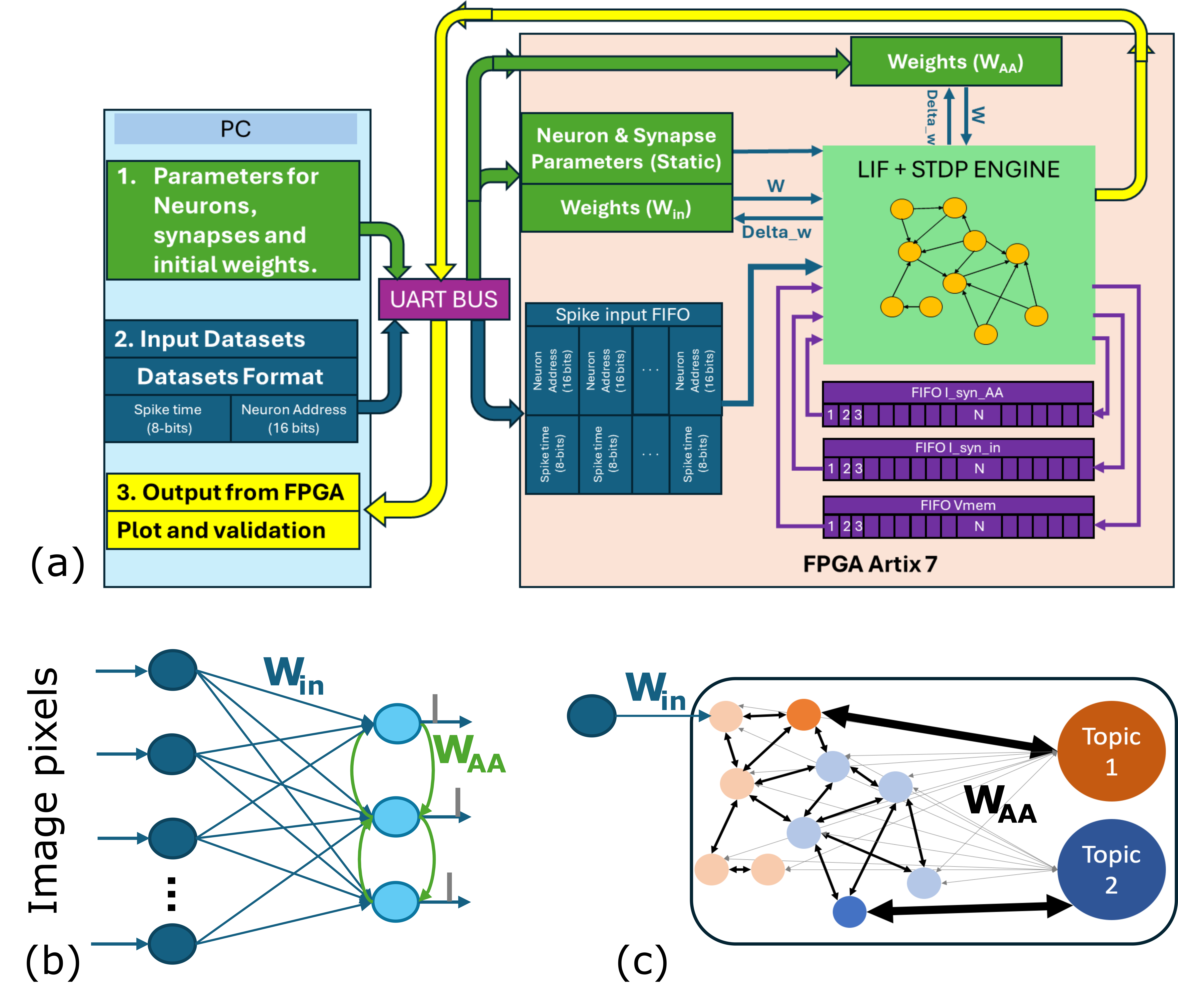
The image is a technical diagram illustrating the architecture and data flow of a spiking neural network (SNN) system implemented on an FPGA (Artix-7). It is divided into three labeled sections: (a) the main system-level architecture showing the interaction between a host PC and the FPGA, (b) a conceptual diagram of the input layer and recurrent network connectivity, and (c) a conceptual diagram of the network's internal structure and topic-based output classification.
### Components/Axes
The diagram is not a chart with axes but a block diagram with interconnected components. The primary components and their labels are:
**Section (a) - System Architecture:**
* **Left Block (PC):**
* Header: `PC`
* Green Box: `1. Parameters for Neurons, synapses and initial weights.`
* Blue Box: `2. Input Datasets`
* Sub-label: `Datasets Format`
| Spike time (8-bits) | Neuron Address (16 bits) |
| :--- | :--- |
* Yellow Box: `3. Output from FPGA`
* Sub-label: `Plot and validation`
* **Central Connection:**
* Purple Box: `UART BUS` (connects PC and FPGA)
* **Right Block (FPGA Artix 7):**
* Header: `FPGA Artix 7`
* Green Box (Top): `Weights (W_AA)`
* Green Box (Middle): `Neuron & Synapse Parameters (Static)` and `Weights (W_in)`
* Large Light Green Box: `LIF + STDP ENGINE` (contains a network diagram of interconnected yellow nodes)
* Blue Box: `Spike input FIFO`
| Neuron Address (16 bits) | Spike time (8-bits) |
| :--- | :--- |
* Purple Boxes (Bottom Right):
* `FIFO I_syn_AA` (with numbered slots 1, 2, 3... N)
* `FIFO I_syn_in` (with numbered slots 1, 2, 3... N)
* `FIFO Vmem` (with numbered slots 1, 2, 3... N)
* **Data Flow Labels:**
* Arrows are labeled with data types: `w`, `Delta_w`.
* A yellow arrow from FPGA back to PC is labeled `Output from FPGA`.
**Section (b) - Network Connectivity (Left):**
* Label: `(b)`
* Input: `Image pixels` (pointing to a column of dark blue nodes).
* Connections: Lines from input nodes to a second layer of light blue nodes are labeled `W_in`.
* Recurrent Connections: Lines between the light blue nodes are labeled `W_AA`.
**Section (c) - Network Structure (Right):**
* Label: `(c)`
* Input Node: A single dark blue node connected via `W_in`.
* Internal Network: A cluster of interconnected nodes (light orange and light blue) with black arrows indicating connections.
* Output Nodes: Two large nodes labeled `Topic 1` (orange) and `Topic 2` (blue).
* Connection Label: `W_AA` is placed near the connections leading to the topic nodes.
### Detailed Analysis
The diagram details a closed-loop system for training and running a spiking neural network on hardware.
1. **Data Flow (Section a):**
* **Configuration & Input (PC to FPGA):** The PC sends static parameters (`Neuron & Synapse Parameters`), initial input weights (`W_in`), and formatted input spike datasets via the `UART BUS`. The dataset format is specified as pairs of `Spike time (8-bits)` and `Neuron Address (16 bits)`.
* **Processing (FPGA):** The FPGA receives spikes into a `Spike input FIFO`. The core processing occurs in the `LIF + STDP ENGINE`, which implements Leaky Integrate-and-Fire neurons with Spike-Timing-Dependent Plasticity learning. This engine uses the static parameters and weights (`W_in`). It also interacts with a separate memory block for recurrent weights (`W_AA`), sending weight updates (`Delta_w`) and receiving current weights (`w`).
* **Internal Data Handling (FPGA):** Three dedicated FIFOs (`I_syn_AA`, `I_syn_in`, `Vmem`) are used to buffer synaptic currents and membrane potentials for the neurons, indexed from 1 to N.
* **Output (FPGA to PC):** Results are sent back to the PC via the `UART BUS` for `Plot and validation`.
2. **Network Models (Sections b & c):**
* **Section (b)** shows a simple two-layer feedforward structure with recurrence. Input `Image pixels` connect via `W_in` to a hidden layer, which has recurrent connections (`W_AA`) among its own neurons.
* **Section (c)** depicts a more complex, possibly trained, network state. An input connects via `W_in` to a recurrently connected internal network. This internal network's activity is then mapped via strong connections (thick black arrows) to distinct `Topic` output nodes, suggesting a classification or clustering function. The label `W_AA` here likely refers to the weights governing these output connections.
### Key Observations
* **Hardware-Software Partitioning:** The design clearly separates the host PC (for data I/O, validation, and high-level control) from the FPGA (for real-time, parallel neural computation).
* **Explicit Data Formats:** The diagram specifies bit-widths for spike data (8-bit time, 16-bit address), which is critical for hardware implementation.
* **Dual Weight Memories:** The architecture maintains separate memory/storage for input weights (`W_in`) and recurrent/associative weights (`W_AA`), allowing for different update rules or access patterns.
* **FIFO-Based Streaming:** The use of multiple FIFOs indicates a streaming data architecture designed to handle continuous spike traffic and maintain pipeline efficiency on the FPGA.
* **Conceptual Progression:** The sequence from (b) to (c) suggests a progression from a basic network topology to a functionally organized one where internal dynamics lead to distinct topic-based outputs.
### Interpretation
This diagram represents a complete hardware-software co-design for a neuromorphic computing system. The core innovation is the implementation of an on-chip learning engine (`LIF + STDP ENGINE`) on an FPGA, enabling the network to adapt its weights (`W_AA`) in real-time based on spike timing.
The system is designed for processing temporal spike data, likely from an event-based sensor (as implied by "Image pixels" in part b). The PC acts as a supervisor, providing the initial network "genome" (parameters and weights) and raw sensory data, then receiving the processed results for analysis. The FPGA handles the computationally intensive, parallel task of simulating thousands of spiking neurons and their plastic synapses.
The transition from diagram (b) to (c) is particularly insightful. It suggests that through the STDP learning rule, the initially random or generic recurrent connections (`W_AA`) in (b) self-organize into a structured network in (c). This structure enables the network to transform a single input pattern into a distributed internal representation that reliably activates specific, semantically meaningful output nodes (`Topic 1`, `Topic 2`). This demonstrates the system's capability for unsupervised feature extraction and classification directly from spike-based data. The entire architecture is a blueprint for building low-power, adaptive, and real-time intelligent sensing systems.
DECODING INTELLIGENCE...