TECHNICAL ASSET FINGERPRINT
53cdd2bf7f47cd8334b4c916
Click to view fullscreen
Press ESC or click to close
FOUND IN PAPERS
EXPERT: gemini-2.5-flash-lite-free VERSION 1
RUNTIME: google-free/gemini-2.5-flash-lite
INTEL_VERIFIED
## Diagram: Energy-Aware Optimization Engine
### Overview
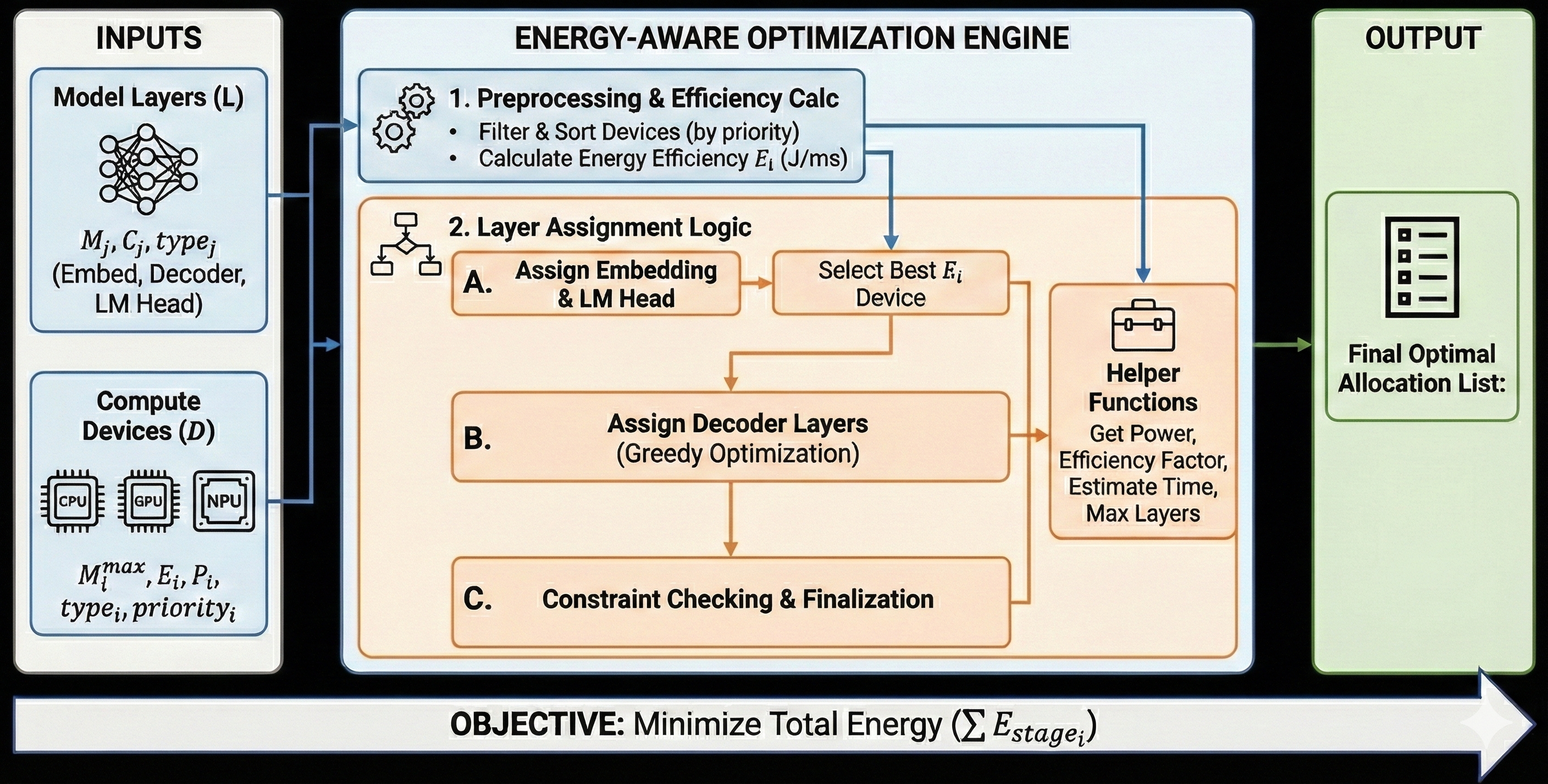
This diagram illustrates the workflow of an "Energy-Aware Optimization Engine." It details the inputs, processing steps, and the final output of a system designed to optimize the allocation of model layers to compute devices with the objective of minimizing total energy consumption.
### Components/Axes
The diagram is structured into three main vertical sections: "INPUTS," the central "ENERGY-AWARE OPTIMIZATION ENGINE," and "OUTPUT." A horizontal bar at the bottom indicates the "OBJECTIVE."
**INPUTS Section:**
* **Model Layers (L):** Represented by a neural network icon.
* Associated variables: $M_j, C_j, type_j$
* Layer types: (Embed, Decoder, LM Head)
* **Compute Devices (D):** Represented by icons for CPU, GPU, and NPU.
* Associated variables: $M_i^{max}, E_i, P_i, type_i, priority_i$
**ENERGY-AWARE OPTIMIZATION ENGINE Section:**
This section is further divided into numbered and lettered steps:
1. **Preprocessing & Efficiency Calc:**
* Icon: Two interlocking gears.
* Sub-steps:
* Filter & Sort Devices (by priority)
* Calculate Energy Efficiency $E_i$ (J/ms)
2. **Layer Assignment Logic:**
* Icon: A flowchart decision symbol.
* **A. Assign Embedding & LM Head:** A rectangular process box.
* **B. Assign Decoder Layers:** A rectangular process box with "(Greedy Optimization)" as a sub-note.
* **Select Best $E_i$ Device:** A rectangular process box.
* **Helper Functions:** A briefcase icon.
* Functions listed: Get Power, Efficiency Factor, Estimate Time, Max Layers.
3. **C. Constraint Checking & Finalization:** A rectangular process box.
**OUTPUT Section:**
* **Final Optimal Allocation List:** Represented by a document icon with a checklist.
**OBJECTIVE Bar:**
* Text: OBJECTIVE: Minimize Total Energy ($\sum E_{stage_i}$)
* Visual: A large white arrow pointing to the right, indicating the direction of the process or optimization goal.
### Detailed Analysis or Content Details
The diagram outlines a sequential process:
1. **Inputs:** The system takes "Model Layers (L)" and "Compute Devices (D)" as input. The model layers are characterized by their memory ($M_j$), computational cost ($C_j$), and type (Embed, Decoder, LM Head). The compute devices are characterized by their maximum memory ($M_i^{max}$), energy efficiency ($E_i$), power ($P_i$), type, and priority.
2. **Preprocessing & Efficiency Calc:** The first step within the engine involves filtering and sorting the available compute devices based on their priority. It also calculates the energy efficiency ($E_i$) for each device, measured in Joules per millisecond (J/ms). This step is crucial for understanding the energy performance of each device.
3. **Layer Assignment Logic:** This is a multi-stage process:
* **A. Assign Embedding & LM Head:** The system first assigns the embedding and LM Head layers. The output of this assignment is then fed into the "Select Best $E_i$ Device" step.
* **Select Best $E_i$ Device:** This box receives input from the "Assign Embedding & LM Head" step and also from the "Preprocessing & Efficiency Calc" step (indicated by a blue arrow pointing to it). This suggests that the selection of the best device for embedding and LM head layers is based on their calculated energy efficiency.
* **B. Assign Decoder Layers (Greedy Optimization):** Following the assignment of embedding and LM head layers, the decoder layers are assigned. This is explicitly stated to use a "Greedy Optimization" strategy.
* **Helper Functions:** A separate box, "Helper Functions," is connected to the "Select Best $E_i$ Device" step and also receives input from the "Preprocessing & Efficiency Calc" step. The functions listed (Get Power, Efficiency Factor, Estimate Time, Max Layers) are likely utilized throughout the assignment logic and constraint checking phases to gather necessary information for decision-making.
4. **C. Constraint Checking & Finalization:** After the layer assignment logic, this step ensures that all constraints are met and finalizes the allocation. This step receives input from the "Assign Decoder Layers" step.
5. **Output:** The final output of the engine is the "Final Optimal Allocation List," which details how the model layers are assigned to the compute devices to achieve the optimization objective.
**Objective:** The overarching goal, clearly stated at the bottom, is to "Minimize Total Energy ($\sum E_{stage_i}$)," where $E_{stage_i}$ likely represents the energy consumed at each stage of the computation on device $i$.
### Key Observations
* The process is highly structured and sequential, moving from input preparation to complex assignment logic and final validation.
* Energy efficiency ($E_i$) is a primary metric, used both in preprocessing and in selecting the best devices for specific layer types.
* The "Helper Functions" box acts as a utility module, providing critical data points for the optimization engine's decision-making.
* The "Greedy Optimization" approach for decoder layers suggests a heuristic method for assignment, aiming for a locally optimal solution at each step.
* The diagram emphasizes the trade-off between computational requirements of model layers and the energy characteristics of available compute devices.
### Interpretation
This diagram describes a sophisticated system for optimizing the deployment of machine learning models on heterogeneous compute hardware. The "Energy-Aware Optimization Engine" aims to intelligently distribute model layers across CPUs, GPUs, and NPUs to minimize overall energy consumption.
The process begins by characterizing both the model's components (layers) and the available hardware (devices). The crucial step of calculating energy efficiency ($E_i$) for each device allows the system to prioritize devices that offer better energy performance for a given task. The subsequent layer assignment logic, particularly the distinction between embedding/LM head layers and decoder layers, suggests that different layer types might have different optimal hardware assignments or require different optimization strategies. The use of a "Greedy Optimization" for decoder layers implies that the system iteratively assigns layers to the most energy-efficient available device at each step, without necessarily guaranteeing a globally optimal solution but providing a practical and efficient approach.
The "Helper Functions" are essential for providing real-time data on power, efficiency, time estimates, and device capacity, which are critical inputs for the greedy assignment and constraint checking. The "Constraint Checking & Finalization" step ensures that the proposed allocation is feasible and adheres to any predefined limits (e.g., maximum layers per device, memory constraints).
Ultimately, the engine produces a "Final Optimal Allocation List" that represents the best possible assignment of layers to devices to achieve the stated objective: minimizing total energy consumption. This is particularly relevant in scenarios where energy efficiency is a critical factor, such as edge computing, mobile devices, or large-scale data centers aiming to reduce operational costs and environmental impact. The diagram effectively visualizes a complex optimization problem being tackled through a systematic and data-driven approach.
DECODING INTELLIGENCE...