## Diagram: Energy-Aware Optimization Engine Flowchart
### Overview
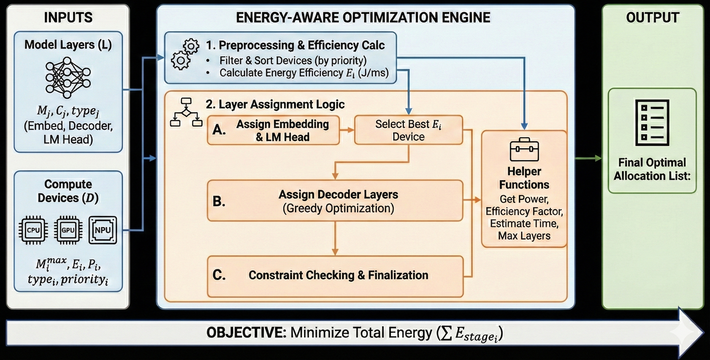
This image is a technical flowchart diagram illustrating a system for optimizing the deployment of AI model layers across heterogeneous compute devices with the primary objective of minimizing total energy consumption. The diagram is structured into three main vertical sections: INPUTS on the left, the core ENERGY-AWARE OPTIMIZATION ENGINE in the center, and the OUTPUT on the right. A horizontal bar at the bottom states the system's objective.
### Components/Axes
The diagram is divided into distinct, color-coded blocks and containers:
**1. INPUTS (Left Column, Light Blue Container)**
* **Top Block: "Model Layers (L)"**
* Icon: A neural network diagram.
* Text: `M_j, C_j, type_j`
* Sub-text: `(Embed, Decoder, LM Head)`
* **Bottom Block: "Compute Devices (D)"**
* Icons: Three chip icons labeled "CPU", "GPU", and "NPU".
* Text: `M_i^max, E_i, P_i, type_i, priority_i`
**2. ENERGY-AWARE OPTIMIZATION ENGINE (Center, Large Light Blue Container)**
This section contains the core processing logic, divided into two main stages.
* **Stage 1: "1. Preprocessing & Efficiency Calc"** (Top, Light Blue Box)
* Icon: Two gears.
* Bullet Points:
* `Filter & Sort Devices (by priority)`
* `Calculate Energy Efficiency E_i (J/ms)`
* **Stage 2: "2. Layer Assignment Logic"** (Main, Large Orange Box)
* Icon: A flowchart/decision tree symbol.
* This stage contains a sequential workflow with three sub-steps (A, B, C) and a supporting "Helper Functions" block.
* **Sub-step A: "Assign Embedding & LM Head"** -> leads to -> **"Select Best E_i Device"**
* **Sub-step B: "Assign Decoder Layers (Greedy Optimization)"**
* **Sub-step C: "Constraint Checking & Finalization"**
* **Helper Functions Block** (Right side of the orange box, connected to steps A and B):
* Icon: A toolbox.
* Text: `Helper Functions`
* List: `Get Power, Efficiency Factor, Estimate Time, Max Layers`
**3. OUTPUT (Right Column, Light Green Container)**
* Icon: A document/list icon.
* Text: `Final Optimal Allocation List:`
**4. Objective Bar (Bottom, Spans Full Width)**
* Text: `OBJECTIVE: Minimize Total Energy (Σ E_stage_i)`
**Flow Arrows:**
* Blue arrows connect the INPUTS blocks to the Optimization Engine.
* Orange arrows show the internal workflow within the "Layer Assignment Logic" stage.
* A green arrow connects the Optimization Engine to the OUTPUT block.
* A large, white, right-pointing arrow forms the background for the objective bar.
### Detailed Analysis
The diagram describes a sequential, multi-stage process:
1. **Input Gathering:** The system takes two primary inputs:
* **Model Layers (L):** Characterized by parameters `M_j` (likely memory), `C_j` (compute cost), and `type_j` (e.g., Embedding, Decoder, LM Head).
* **Compute Devices (D):** Characterized by `M_i^max` (max memory), `E_i` (energy efficiency), `P_i` (power), `type_i`, and `priority_i`.
2. **Preprocessing & Efficiency Calculation (Stage 1):**
* Devices are filtered and sorted based on their `priority_i`.
* The energy efficiency `E_i` for each device is calculated, with units given as Joules per millisecond (J/ms).
3. **Layer Assignment Logic (Stage 2):** This is a three-phase greedy optimization process:
* **Phase A:** The special "Embedding" and "LM Head" layers are assigned first. The device with the best energy efficiency (`E_i`) is selected for these layers.
* **Phase B:** The remaining "Decoder Layers" are assigned using a greedy optimization algorithm. This phase interacts with "Helper Functions" to retrieve necessary data like power, efficiency factors, time estimates, and maximum layer capacity.
* **Phase C:** The proposed assignment undergoes constraint checking and is finalized.
4. **Output:** The final result is an "Optimal Allocation List," which presumably maps each model layer to a specific compute device.
5. **Objective:** The overarching goal, stated explicitly, is to minimize the sum of energy consumed across all stages (`Σ E_stage_i`).
### Key Observations
* **Structured Workflow:** The process is highly structured, moving from data collection (Inputs) to preprocessing, then to a phased assignment logic, and finally to output.
* **Mathematical Formalism:** The use of variables (`M_j`, `E_i`, `Σ E_stage_i`) indicates a quantitative, algorithmic approach to the optimization problem.
* **Greedy Algorithm:** The assignment of decoder layers explicitly uses a "Greedy Optimization" strategy, suggesting a heuristic that makes locally optimal choices at each step.
* **Heterogeneity:** The system is designed for heterogeneous environments, explicitly listing CPU, GPU, and NPU as device types.
* **Helper Functions:** The presence of a dedicated block for helper functions indicates that the core logic relies on several sub-routines for data retrieval and estimation.
### Interpretation
This diagram represents a system for **energy-efficient AI model partitioning and deployment**. It addresses the challenge of running large AI models (like LLMs, given the "LM Head" and "Decoder" references) across a mix of available hardware (CPUs, GPUs, NPUs) in a way that minimizes total energy consumption.
The process is investigative and systematic: it first characterizes both the workload (model layers) and the resources (devices), then uses a prioritized, efficiency-driven heuristic to assign workloads. The "greedy" approach for decoder layers suggests a practical trade-off between optimality and computational complexity. The final output is not just a performance plan, but an *energy-optimized* execution plan. This is critical for sustainable AI, edge computing, and cost reduction in data centers. The diagram effectively communicates the logical flow and key parameters of such an optimization engine, serving as a blueprint for its implementation.