## Diagram: Logical AND Gate Loop Between Nodes A and B
### Overview
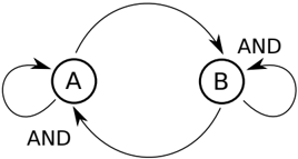
The diagram depicts a cyclical logical relationship between two nodes labeled **A** and **B**, connected by bidirectional arrows labeled **"AND"**. The structure forms a closed loop, with arrows indicating directional dependencies between the nodes.
### Components/Axes
- **Nodes**:
- **A**: A circular node on the left side of the diagram.
- **B**: A circular node on the right side of the diagram.
- **Arrows**:
- Four bidirectional arrows connect **A** and **B**, each labeled **"AND"**.
- Two arrows point from **A** to **B** (top and bottom).
- Two arrows point from **B** to **A** (top and bottom).
- **Flow Direction**:
- The arrows form a continuous loop, suggesting mutual dependency between **A** and **B**.
### Detailed Analysis
- **Textual Labels**:
- Nodes: **A**, **B**.
- Arrows: **"AND"** (repeated four times).
- **Spatial Grounding**:
- **A** is positioned on the left; **B** on the right.
- Arrows are evenly distributed around the loop, with no overlap or additional labels.
- **Legend/Key**: No explicit legend is present, but the repeated use of **"AND"** on arrows implies a logical operator governing the relationship.
### Key Observations
1. The diagram represents a **bidirectional AND gate** system, where both **A** and **B** must be true simultaneously for the flow to persist.
2. The cyclical nature implies a **feedback loop**, where the state of **A** depends on **B**, and vice versa.
3. No numerical values, trends, or outliers are present; the focus is purely on logical relationships.
### Interpretation
This diagram illustrates a **closed-loop logical system** where **A** and **B** are interdependent via AND gates. For the system to function:
- **A** requires **B** to be true (via the top and bottom arrows from **A** to **B**).
- **B** requires **A** to be true (via the top and bottom arrows from **B** to **A**).
This creates a **mutual dependency**: if either **A** or **B** fails, the entire loop collapses. The repetition of **"AND"** emphasizes that both conditions must hold at all times, highlighting a **conjunctive relationship** critical to the system’s stability.
No numerical data or trends are provided, so the analysis is limited to structural and logical interpretation.