## Diagram: Mechanical/Optical System Schematic
### Overview
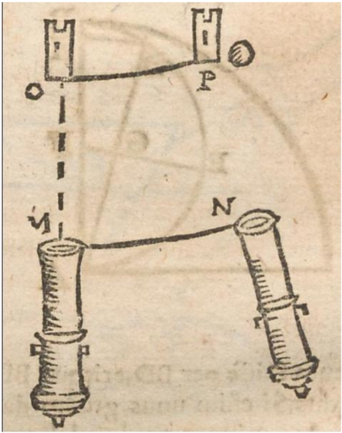
The image depicts a hand-drawn technical diagram on aged, textured paper. It illustrates a system with two vertical towers (labeled **O** and **P**) connected by a horizontal line, and two cylindrical components (labeled **M** and **N**) connected by another horizontal line. A compass rose (with **N** and **S** markings) and a circular symbol labeled **P** are present in the background. Faded, illegible text appears in the lower portion of the image.
### Components/Axes
- **Labels**:
- **O**: Top-left tower (rectangular with crenellated top).
- **P**: Top-right tower (similar to **O**).
- **M**: Bottom-left cylinder (with horizontal ridges and a conical base).
- **N**: Bottom-right cylinder (identical to **M**).
- **Compass Rose**: Background element with **N** (north) and **S** (south) labels.
- **Circle**: Background element labeled **P** (possibly a reference point).
- **Connections**:
- Horizontal line links **O** and **P** (top tier).
- Horizontal line links **M** and **N** (bottom tier).
- Vertical dashed line connects **O** to **M** (left side).
- Vertical dashed line connects **P** to **N** (right side).
- **Background Elements**:
- Faded compass rose (centered, overlapping the diagram).
- Circular symbol labeled **P** (upper-right quadrant).
- Faded text (illegible, lower portion).
### Detailed Analysis
- **Towers (O, P)**:
- Rectangular with crenellated tops (suggesting medieval or fortified design).
- Positioned symmetrically at the top of the diagram.
- **Cylinders (M, N)**:
- Vertical, ridged bodies with conical bases (resembling pistons or telescopic components).
- Positioned symmetrically at the bottom of the diagram.
- **Connections**:
- Top and bottom tiers are linked horizontally, implying a transfer mechanism (e.g., force, motion, or data).
- Dashed vertical lines suggest alignment or measurement relationships between top and bottom components.
- **Compass Rose**:
- Indicates directional orientation (north-south axis).
- May imply the system’s alignment or operational context (e.g., astronomical, navigational).
- **Faded Text**:
- Unreadable due to paper degradation.
- Likely explanatory notes or annotations (e.g., measurements, instructions).
### Key Observations
1. **Symmetry**: The system is balanced left-right, with mirrored components (**O**/**P** and **M**/**N**).
2. **Hierarchical Structure**: Top-tier towers (**O**, **P**) appear to govern or influence the bottom-tier cylinders (**M**, **N**).
3. **Directionality**: The compass rose suggests the system’s orientation is critical (e.g., alignment with celestial or geographic north).
4. **Aged Medium**: Paper texture and faded text indicate historical or archival significance.
### Interpretation
This diagram likely represents a mechanical or optical system requiring precise alignment. The towers (**O**, **P**) may act as reference points or supports, while the cylinders (**M**, **N**) could be movable parts (e.g., lenses, mirrors, or pistons). The horizontal connections imply a transfer of motion, force, or information between tiers. The compass rose reinforces the importance of directional accuracy, possibly for applications like surveying, astronomy, or navigation. The faded text hints at lost operational details, suggesting the diagram was part of a larger, now-degraded technical manual.
**Notable Anomalies**:
- The circle labeled **P** overlaps the compass rose but lacks clear contextual integration.
- The dashed lines’ purpose (e.g., measurement, alignment) is inferred but not explicitly stated.