## Diagram: Early Ballistics Illustration
### Overview
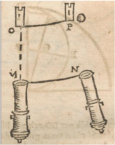
The image is a hand-drawn diagram illustrating an early concept related to ballistics or projectile motion. It depicts two towers, two cannon-like objects, and lines representing trajectories or lines of sight. The diagram appears to be from an old book or manuscript, given the paper's texture and the style of the drawing.
### Components/Axes
* **Towers:** Two rectangular structures resembling towers are positioned at the top of the diagram. They are labeled "O" (left tower) and "P" (right tower).
* **Cannons:** Two cannon-like objects are at the bottom of the diagram. They are labeled "V" (left cannon) and "N" (right cannon).
* **Trajectory Lines:** Solid lines connect the towers to the cannons, representing a possible trajectory or line of sight.
* **Dashed Line:** A dashed line extends vertically downward from the left tower ("O") towards the left cannon ("V").
* **Projectile:** A small circle is drawn near the right tower ("P"), possibly representing a projectile.
* **Background:** Faint lines and shapes are visible in the background, suggesting additional elements or context that are not clearly defined.
### Detailed Analysis
* **Towers:**
* Tower "O" is positioned slightly higher than tower "P".
* A solid line connects tower "O" to cannon "V".
* A dashed line extends from the base of tower "O" to cannon "V".
* A solid line connects tower "P" to cannon "N".
* A projectile (small circle) is located to the right of tower "P".
* **Cannons:**
* Cannon "V" is oriented vertically.
* Cannon "N" is oriented at an angle.
* The solid lines connecting the towers to the cannons appear to represent a line of sight or trajectory.
* **Trajectory Lines:**
* The line connecting tower "O" to cannon "V" is horizontal.
* The line connecting tower "P" to cannon "N" is angled downward.
### Key Observations
* The diagram seems to illustrate a relationship between the towers and the cannons, possibly related to aiming or trajectory calculation.
* The different orientations of the cannons suggest a consideration of angles or elevation in projectile motion.
* The dashed line from tower "O" to cannon "V" might represent a vertical reference or a plumb line.
### Interpretation
The diagram likely represents an early attempt to understand and visualize the principles of ballistics. The towers could represent observation points, while the cannons represent the launching devices. The lines connecting them may illustrate the path of a projectile or the line of sight required for aiming. The different orientations of the cannons and the presence of the projectile suggest an awareness of factors like angle of elevation and trajectory. The diagram is a simplified representation, lacking precise measurements or calculations, but it captures the essential elements of projectile motion in a visual form. The diagram could be used to explain the relationship between the angle of the cannon and the distance the projectile travels.