TECHNICAL ASSET FINGERPRINT
54a8749ee79248d6af1f2e3a
Click to view fullscreen
Press ESC or click to close
FOUND IN PAPERS
EXPERT: healer-alpha-free VERSION 1
RUNTIME: free/openrouter/healer-alpha
INTEL_VERIFIED
## Diagram: Comparison of Code Generation Approaches for a Visual Pattern Task
### Overview
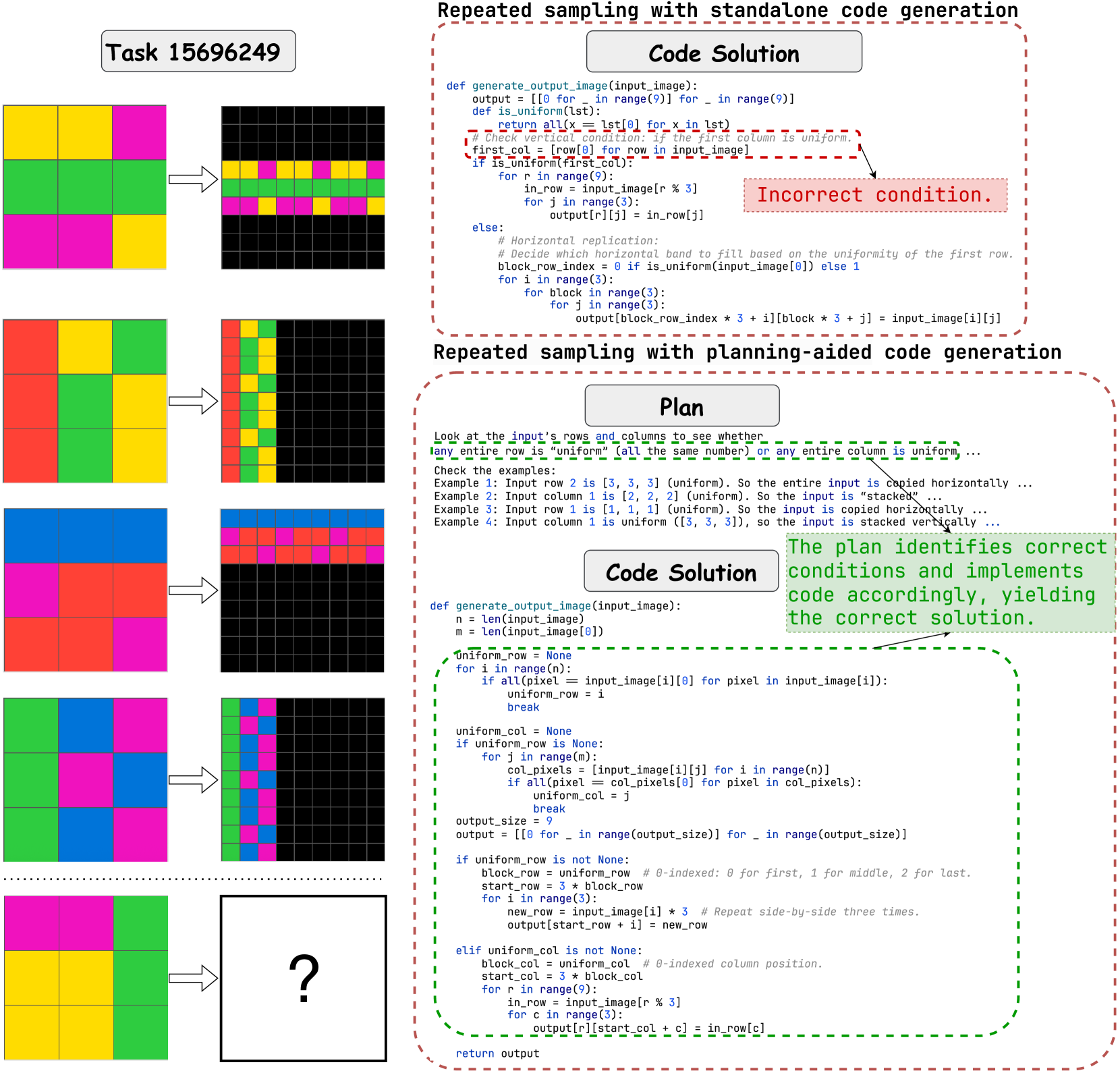
This image is a technical diagram comparing two methods for generating code to solve a visual pattern recognition task (Task 15696249). The task involves transforming a 3x3 input grid of colored squares into a 9x9 output grid based on specific rules. The diagram contrasts a flawed "standalone code generation" approach with a successful "planning-aided code generation" approach, using visual examples and annotated code snippets.
### Components/Axes
The diagram is divided into two primary vertical sections:
1. **Left Column (Visual Examples):**
* **Header:** "Task 15696249"
* **Content:** Five rows of input-output pairs. Each row shows:
* A 3x3 input grid (left).
* An arrow pointing to a 9x9 output grid (right).
* The grids use solid colors: yellow, magenta (pink), green, red, and blue.
* **Purpose:** Demonstrates the transformation rule. The output pattern (horizontal or vertical replication) depends on whether the input has a uniform row or column.
2. **Right Column (Code & Explanation):**
* **Top Section:** Titled "Repeated sampling with standalone code generation".
* Contains a Python function `generate_output_image` in a code block.
* A red dashed box highlights a specific condition: `if is_uniform(first_col):`.
* A red annotation points to this line with the text: "Incorrect condition."
* **Bottom Section:** Titled "Repeated sampling with planning-aided code generation".
* Contains a "Plan" text block explaining the logic.
* Contains a corrected "Code Solution" Python function.
* A green dashed box surrounds the core logic of the corrected code.
* A green annotation states: "The plan identifies correct conditions and implements code accordingly, yielding the correct solution."
### Detailed Analysis
**Visual Examples (Left Column):**
* **Example 1 (Top):** Input has a uniform middle row (all green). Output shows that row replicated horizontally three times to form a 3x9 band, placed in the middle of the 9x9 grid.
* **Example 2:** Input has a uniform first column (all red). Output shows that column replicated vertically three times to form a 9x3 band, placed on the left of the 9x9 grid.
* **Example 3:** Input has a uniform top row (all blue). Output shows horizontal replication of that row.
* **Example 4:** Input has a uniform first column (all magenta). Output shows vertical replication of that column.
* **Example 5 (Bottom):** Input has a uniform middle column (all green). The output is a question mark, indicating this is the test case for the final solution.
**Code Transcription & Analysis (Right Column):**
**1. Standalone Code Generation (Flawed):**
```python
def generate_output_image(input_image):
output = [[0 for _ in range(9)] for _ in range(9)]
def is_uniform(lst):
return all(x == lst[0] for x in lst)
# Check vertical condition: if the first column is uniform.
first_col = [row[0] for row in input_image]
if is_uniform(first_col): # <-- HIGHLIGHTED AS "Incorrect condition."
for r in range(9):
in_row = input_image[r % 3]
for j in range(3):
output[r][j] = in_row[j]
else:
# Horizontal replication:
# Decide which horizontal band to fill based on the uniformity of the first row.
block_row_index = 0 if is_uniform(input_image[0]) else 1
for i in range(3):
for block in range(3):
for j in range(3):
output[block_row_index * 3 + i][block * 3 + j] = input_image[i][j]
```
* **Error:** The logic is flawed. It only checks if the *first column* is uniform to decide on vertical replication. If not, it defaults to a horizontal replication logic that only checks the *first row*. This fails for cases where a uniform row is not the first row (e.g., Example 1) or a uniform column is not the first column (e.g., Example 5).
**2. Planning-Aided Code Generation (Corrected):**
* **Plan Text:**
> Look at the input's rows and columns to see whether any entire row is "uniform" (all the same number) or any entire column is uniform...
> Check the examples:
> Example 1: Input row 2 is [3, 3, 3] (uniform). So the entire input is copied horizontally ...
> Example 2: Input column 1 is [2, 2, 2] (uniform). So the input is "stacked" ...
> Example 3: Input row 1 is [1, 1, 1] (uniform). So the input is copied horizontally ...
> Example 4: Input column 1 is uniform ([3, 3, 3]), so the input is stacked vertically ...
* **Corrected Code Solution:**
```python
def generate_output_image(input_image):
n = len(input_image)
m = len(input_image[0])
uniform_row = None
for i in range(n):
if all(pixel == input_image[i][0] for pixel in input_image[i]):
uniform_row = i
break
uniform_col = None
if uniform_row is None:
for j in range(m):
col_pixels = [input_image[i][j] for i in range(n)]
if all(pixel == col_pixels[0] for pixel in col_pixels):
uniform_col = j
break
output_size = 9
output = [[0 for _ in range(output_size)] for _ in range(output_size)]
if uniform_row is not None:
block_row = uniform_row # 0-indexed: 0 for first, 1 for middle, 2 for last.
start_row = 3 * block_row
for i in range(3):
new_row = input_image[i] * 3 # Repeat side-by-side three times.
output[start_row + i] = new_row
elif uniform_col is not None:
block_col = uniform_col # 0-indexed column position.
start_col = 3 * block_col
for r in range(9):
in_row = input_image[r % 3]
for c in range(3):
output[r][start_col + c] = in_row[c]
return output
```
* **Key Correction:** The plan correctly identifies that the code must search *all* rows and *all* columns for uniformity, not just the first of each. The code implements this by first searching for any uniform row. If none is found, it then searches for any uniform column. The replication logic is then applied based on the index of the found uniform row/column.
### Key Observations
1. **Logical Flaw vs. Robust Plan:** The standalone code fails because it makes a premature, incorrect assumption (only checking the first row/column). The planning-aided approach succeeds by first analyzing the problem requirements from the examples.
2. **Visual-Code Correlation:** The green output grids in the examples directly correspond to the logic in the corrected code. For instance, the vertical red band in Example 2's output is generated by the `elif uniform_col is not None:` block.
3. **Spatial Layout of Annotations:** The red "Incorrect condition" annotation is placed in the top-right, directly pointing to the flawed line. The green explanatory annotation is placed in the center-right, summarizing the success of the planned approach.
4. **Task Ambiguity Resolution:** The plan text explicitly resolves the ambiguity in the task description by inferring the rule from the provided examples: "if any row is uniform, replicate horizontally; if any column is uniform, replicate vertically."
### Interpretation
This diagram serves as a pedagogical comparison between two paradigms in automated code generation. It argues that **explicit planning and problem analysis** (the "planning-aided" approach) lead to correct and generalizable solutions, whereas **direct code generation** (the "standalone" approach) is prone to logical errors from making oversimplified assumptions.
The underlying message is that for tasks involving pattern recognition and rule deduction from examples (common in AI benchmarks like ARC), a model must first "understand" the pattern by forming a plan before writing code. The incorrect condition in the first code block is a symptom of jumping to implementation without this understanding. The successful second approach demonstrates that decomposing the problem—first identifying the transformation rule, then implementing checks for that rule—yields robust results. This highlights the importance of intermediate reasoning steps in complex problem-solving for AI systems.
DECODING INTELLIGENCE...