TECHNICAL ASSET FINGERPRINT
55084b1e542e618b57b422e5
Click to view fullscreen
Press ESC or click to close
FOUND IN PAPERS
EXPERT: healer-alpha-free VERSION 1
RUNTIME: free/openrouter/healer-alpha
INTEL_VERIFIED
## Technical Diagram: Heterogeneous Computing System Architecture
### Overview
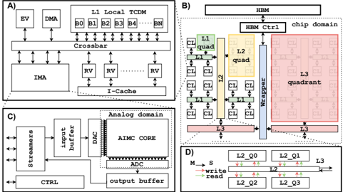
The image presents a composite technical diagram divided into four labeled panels (A, B, C, D), illustrating different aspects of a specialized computing system architecture. The diagrams depict a digital processing unit, a chip-level memory hierarchy, an analog processing domain, and a network-on-chip interconnect structure. The overall theme is a heterogeneous system combining digital logic, analog processing, and advanced memory architectures.
### Components/Axes
The image is segmented into four distinct panels:
* **Panel A (Top-Left):** A block diagram of a digital processing unit or core.
* **Panel B (Top-Right):** A hierarchical diagram of a chip's memory and core organization.
* **Panel C (Bottom-Left):** A block diagram of an analog processing domain.
* **Panel D (Bottom-Right):** A schematic of a network-on-chip or interconnect fabric.
### Detailed Analysis
#### **Panel A: Digital Processing Unit Block Diagram**
* **Components & Labels:**
* **EV:** A block at the top-left.
* **DMA:** A block to the right of EV.
* **IMA:** A large block in the lower-left.
* **Crossbar:** A central interconnect block.
* **L1 Local TCIM:** A memory block at the top, subdivided into four banks labeled **B0**, **B1**, **B2**, **B3**.
* **RV:** Multiple blocks (at least 8 visible) arranged below the Crossbar and to the right of the IMA.
* **I-Cache:** An instruction cache block at the bottom.
* **Flow & Relationships:** Bidirectional arrows connect the EV, DMA, and IMA to the central Crossbar. The Crossbar connects to the L1 Local TCIM banks (B0-B3) and to the multiple RV blocks. The I-Cache is connected to the IMA. This suggests a architecture where a main processing unit (IMA) communicates via a crossbar with specialized units (RV), local memory, and direct memory access (DMA).
#### **Panel B: Chip-Level Memory Hierarchy**
* **Components & Labels:**
* **HBM:** High Bandwidth Memory block at the very top.
* **HBM Ctrl:** HBM Controller block below HBM.
* **chip domain:** A label indicating the scope of the diagram below the HBM Ctrl.
* **Memory Hierarchy (Color-Coded):**
* **L1 (Green):** Labeled "L1 Quad". Contains multiple small squares (cores/caches) connected in a grid.
* **L2 (Yellow):** Labeled "L2 quad". A larger block encompassing multiple L1 Quads.
* **L3 (Pink/Red):** Labeled "L3 quadrant". The largest block, encompassing multiple L2 quads.
* **Interconnects:**
* **Router:** A vertical blue bar connecting the L2 and L3 domains.
* **Links:** Horizontal red bars labeled "Link" connecting the L3 quadrant to the Router and to other L3 quadrants (implied).
* **Spatial Grounding & Flow:** The hierarchy is spatially organized from fine-grained (L1, top-left) to coarse-grained (L3, bottom-right). Data/control flows vertically from HBM down through the controller into the chip domain, then horizontally across the L3 quadrants via links and routers, and finally down into the L2 and L1 cores.
#### **Panel C: Analog Domain Block Diagram**
* **Components & Labels:**
* **Analog domain:** Label at the top.
* **Streams:** Input block on the far left.
* **input buffer:** Block receiving data from Streams.
* **CTRL:** Control block below the input buffer.
* **AINC CORE:** The central processing core.
* **DAC:** Digital-to-Analog Converter, positioned between the input buffer and the AINC CORE.
* **ADC:** Analog-to-Digital Converter, positioned between the AINC CORE and the output buffer.
* **output buffer:** Block receiving data from the ADC.
* **Flow:** The data flow is clearly left-to-right: `Streams -> input buffer -> DAC -> AINC CORE -> ADC -> output buffer`. The CTRL block has connections to the input buffer, AINC CORE, and output buffer, indicating it manages the analog processing pipeline.
#### **Panel D: Network-on-Chip Interconnect**
* **Components & Labels:**
* **L2_Q0, L2_Q1, L2_Q2, L2_Q3:** Four quadrants representing L2 memory or processing clusters.
* **L3:** A block on the right, representing a higher-level shared memory or cache.
* **M -> S:** A label at the top-left, likely indicating "Master to Slave" or "Memory to Slave" communication direction.
* **write/read:** Labels on arrows indicating the type of transaction.
* **Flow & Relationships:** The diagram shows a 2x2 grid of L2 quadrants (Q0-Q3). Arrows indicate communication paths:
* Horizontal arrows between L2_Q0 and L2_Q1, and between L2_Q2 and L2_Q3.
* Vertical arrows between L2_Q0 and L2_Q2, and between L2_Q1 and L2_Q3.
* All quadrants have paths leading to the L3 block on the right.
* The arrows are color-coded (red and green) and labeled for "write" and "read" operations, showing a mesh network for intra-L2 communication and a shared link to L3.
### Key Observations
1. **Hierarchical Design:** The system exhibits a clear hierarchy at multiple levels: within a core (Panel A), across cores on a chip (Panel B), and in the memory subsystem (Panels B & D).
2. **Heterogeneous Integration:** The architecture integrates traditional digital logic (Panel A), advanced 3D-stacked memory (HBM in Panel B), analog computing elements (Panel C), and sophisticated on-chip networks (Panel D).
3. **Parallelism:** The repeated structures (RV blocks in A, L1/L2 quads in B, L2 quadrants in D) indicate a design focused on massive parallel processing.
4. **Specialized Data Paths:** The analog domain (Panel C) has a dedicated, linear pipeline separate from the digital domains, suggesting it's optimized for specific signal processing tasks.
### Interpretation
This composite diagram illustrates the architecture of a high-performance, domain-specific computing chip, likely designed for workloads like AI/ML inference, scientific simulation, or signal processing. The **Peircean investigative reading** suggests the following:
* **Iconic Representation:** Each panel is an icon representing a fundamental computing pillar: computation (A), memory hierarchy (B), analog signal processing (C), and communication (D).
* **Indexical Cues:** The arrows and connections index the flow of data and control, revealing a system where data moves from high-bandwidth memory (HBM), through a deep cache hierarchy (L3->L2->L1), into processing cores (RV, IMA), with possible offloads to a specialized analog core for certain operations. The network-on-chip (D) is the circulatory system enabling this data movement.
* **Symbolic Synthesis:** Together, the diagrams symbolize a move away from homogeneous CPU-centric designs. They represent a **trend towards heterogeneous system-on-chip (SoC) architectures** where different types of processors (digital, analog) and memory technologies are integrated and interconnected by sophisticated networks to achieve efficiency and performance for specific application domains. The presence of an analog core (AINC) is particularly notable, pointing to emerging **in-memory or near-memory computing** paradigms that aim to reduce the energy cost of data movement by performing computations directly on analog signals. The system's complexity suggests it is a cutting-edge design where memory bandwidth, parallelism, and specialized processing are the primary performance drivers.
DECODING INTELLIGENCE...