## Diagram: System Architecture for Federated Learning/Feature Alignment
### Overview
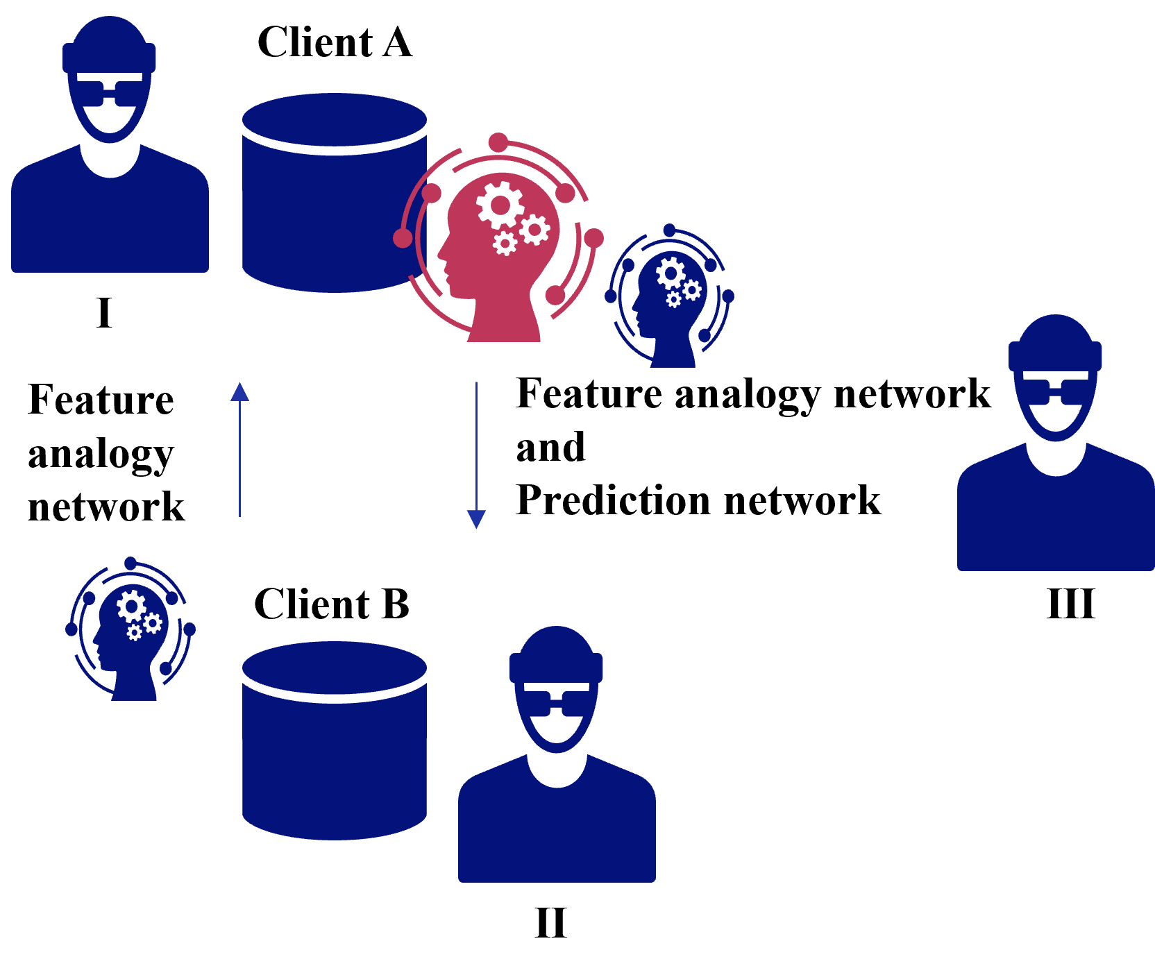
The image is a conceptual system architecture diagram illustrating the interaction between two clients (Client A and Client B) and a third entity (Figure III). The diagram depicts a process involving "Feature analogy networks" and a "Prediction network," likely representing a federated learning or privacy-preserving machine learning framework where data representations are aligned between clients before a final prediction is made.
### Components/Axes
* **Entities (Icons):**
* **Figure I:** A stylized icon of a person wearing a hat and sunglasses, positioned at the top-left.
* **Figure II:** A stylized icon of a person wearing a hat and sunglasses, positioned at the bottom-center.
* **Figure III:** A stylized icon of a person wearing a hat and sunglasses, positioned on the right.
* **Data Stores:**
* **Client A:** A dark blue cylinder icon, positioned at the top-left, associated with Figure I.
* **Client B:** A dark blue cylinder icon, positioned at the bottom-left, associated with Figure II.
* **AI/Network Components:**
* **Red Brain Icon:** Located to the right of Client A. It contains gear symbols.
* **Blue Brain Icon (Left):** Located to the left of Client B. It contains gear symbols.
* **Blue Brain Icon (Right):** Located to the right of the Red Brain icon, closer to Figure III. It contains gear symbols.
* **Flow Indicators:**
* **Upward Arrow:** Positioned between the Client B/Blue Brain cluster and the Client A/Red Brain cluster.
* **Downward Arrow:** Positioned between the Client A/Red Brain cluster and the Client B/Blue Brain cluster.
### Content Details
* **Textual Labels:**
* **"Client A"**: Located above the top cylinder.
* **"Client B"**: Located above the bottom cylinder.
* **"I"**: Located below the top-left figure.
* **"II"**: Located below the bottom-center figure.
* **"III"**: Located below the right-side figure.
* **"Feature analogy network"**: This label appears twice. Once on the left side, vertically aligned between the two client clusters, and again as part of the label on the right.
* **"Feature analogy network and Prediction network"**: Located on the right side of the diagram, between the central brain icons and Figure III.
### Key Observations
* **Color Coding:** The diagram uses a distinct color scheme. The "Client A" side is associated with a red-colored brain icon, while the "Client B" side is associated with a blue-colored brain icon.
* **Bidirectional Flow:** The vertical arrows between the two client clusters suggest a continuous, iterative exchange of information (likely model parameters or gradients) between Client A and Client B.
* **Network Separation:** The "Feature analogy network" appears to be a shared or distributed component between the two clients, while the "Prediction network" is positioned closer to Figure III, suggesting it is the final stage of the pipeline.
* **Spatial Grouping:** The diagram is split into two distinct operational zones: the left side (Clients A and B interacting via Feature Analogy) and the right side (the final output/prediction stage involving Figure III).
### Interpretation
This diagram represents a **Federated Learning or Cross-Silo Learning architecture**.
* **Mechanism:** The "Feature analogy network" suggests that the system is designed to align data features between two disparate clients (A and B) that likely cannot share raw data due to privacy constraints. By using an analogy network, the system learns to map data from Client A and Client B into a common latent space.
* **Process Flow:** The bidirectional arrows indicate that the clients are likely performing collaborative training. They exchange information to update their respective "Feature analogy networks" until they reach a consensus or aligned representation.
* **Final Stage:** Once the features are aligned, the information is passed to the "Prediction network" (associated with Figure III). This implies that Figure III acts as the central server or the final inference engine that utilizes the aligned features from both clients to perform a specific prediction task.
* **Peircean/Inference:** The repetition of "Feature analogy network" on the left and right suggests that the analogy network is the *bridge* that enables the "Prediction network" to function effectively across heterogeneous data sources. The use of "hacker/user" icons (I, II, III) suggests this might be a security-focused or privacy-centric implementation where the identity of the data owners is protected.