## Diagram: Network Transformation
### Overview
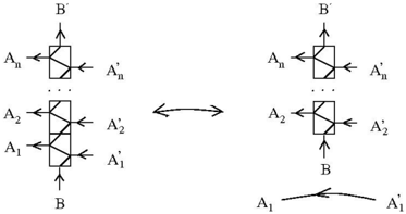
The image presents a diagram illustrating a network transformation or equivalence. It shows two different configurations of interconnected components, with an arrow indicating their interconvertibility. The diagram appears to represent a system where inputs are processed and outputs are generated, with a transformation occurring between two different arrangements of these components.
### Components/Axes
* **Components:** The diagram features rectangular blocks, each with internal lines suggesting a processing or routing function. These blocks are labeled with "A" and "B" variants, with numerical subscripts for the "A" variants.
* **Arrows:** Arrows indicate the direction of flow or interaction between the components.
* **Labels:** The labels include:
* A₁, A'₁
* A₂, A'₂
* Aₙ, A'ₙ
* B, B'
* **Symbol:** A double-headed arrow in the center indicates a transformation or equivalence between the two configurations.
### Detailed Analysis
The diagram can be divided into two main configurations, left and right, connected by a transformation arrow.
**Left Configuration:**
* A series of blocks labeled A₁, A₂, ..., Aₙ are stacked vertically.
* Each A block has an input arrow on the left (A₁, A₂, Aₙ) and an output arrow on the right (A'₁, A'₂, A'ₙ).
* The bottom block is labeled "B" and has an upward-pointing output arrow.
**Right Configuration:**
* A series of blocks labeled A₂, ..., Aₙ are stacked vertically.
* Each A block has an input arrow on the left (A₂, Aₙ) and an output arrow on the right (A'₂, A'ₙ).
* The top block is labeled "B'" and has an upward-pointing output arrow.
* The bottom of the diagram has an input labeled A₁ and an output labeled A'₁.
**Transformation:**
* A double-headed arrow connects the two configurations, indicating that they are equivalent or can be transformed into each other.
### Key Observations
* The transformation appears to involve rearranging the order or connections of the components.
* The "A" components seem to be processed sequentially in the left configuration, while in the right configuration, A₁ is separated from the rest.
* The "B" component changes its position and label (B to B') during the transformation.
### Interpretation
The diagram likely represents a network or system where the order of processing or connections between components can be rearranged without changing the overall functionality. The transformation suggests that the system is invariant under certain rearrangements. The separation of A₁ in the right configuration might indicate a specific optimization or simplification that can be achieved through this transformation. The diagram could be used to illustrate concepts in network theory, signal processing, or other fields where interconnected components are used to perform a specific task.