\n
## Diagram: Shear Force Distribution in a Rectangular Beam
### Overview
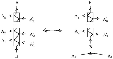
The image depicts a schematic diagram illustrating the shear force distribution within a rectangular beam subjected to a vertical load. It shows two views of the beam, one representing the initial state and the other representing a transformed state after considering shear stress. A curved arrow indicates a transformation or relationship between the two views.
### Components/Axes
The diagram consists of:
* **Rectangular Beam Sections:** Two rectangular sections are shown, representing the beam's cross-section.
* **Vertical Forces (B & B'):** Labeled 'B' at the bottom of each beam section, indicating a downward vertical force. 'B'' is also labeled at the top of each section.
* **Horizontal Forces (A1, A2, ... An & A'1, A'2, ... A'n):** Labeled 'A1' through 'An' on the left side of the beam and 'A'1 through 'A'n on the right side, representing horizontal shear forces.
* **Diagonal Braces:** Diagonal lines within the rectangular sections, representing the shear stress path.
* **Transformation Arrow:** A double-headed arrow positioned between the two beam sections, indicating a transformation or relationship.
* **Curved Arrow (A1 to A'1):** A curved arrow at the bottom of the diagram, showing the transformation of force A1 to A'1.
### Detailed Analysis / Content Details
The diagram illustrates the following:
* **Initial State (Left):** The left side shows a rectangular beam section with vertical forces 'B' and 'B'' acting at the top and bottom, respectively. Horizontal shear forces 'A1' through 'An' are applied on the left side, and corresponding forces 'A'1 through 'A'n are applied on the right side. Diagonal braces are present within the rectangle.
* **Transformed State (Right):** The right side shows a similar rectangular beam section, but the diagonal braces are more prominent, and the horizontal forces are represented as 'A'1' through 'A'n'. The curved arrow indicates that the horizontal force 'A1' transforms into 'A'1.
* **Force Distribution:** The diagram suggests that the vertical shear force 'B' is resolved into horizontal shear forces 'A1' through 'An' and 'A'1 through 'A'n', and these forces are transmitted through the diagonal braces within the beam.
* **Transformation:** The transformation indicated by the double-headed arrow and the curved arrow suggests a change in the distribution of shear stresses within the beam.
### Key Observations
* The diagram is a simplified representation of shear stress distribution.
* The diagonal braces represent the path of shear stress within the beam.
* The transformation suggests that the shear stress distribution changes as the load is applied.
* The diagram does not provide numerical values for the forces.
### Interpretation
The diagram illustrates the concept of shear stress distribution in a rectangular beam. The vertical shear force 'B' is resolved into horizontal shear forces that are transmitted through the diagonal braces. The transformation suggests that the shear stress distribution is not uniform and changes as the load is applied. This diagram is likely used to explain the underlying principles of shear stress in structural mechanics. The diagram is a conceptual illustration and does not provide quantitative data. It is a qualitative representation of how shear forces are distributed within a beam. The curved arrow suggests that the shear force is being redirected or transformed, possibly due to the material properties or geometry of the beam. The diagram is a simplified model and does not account for factors such as stress concentrations or material anisotropy.