## Technical Diagram: NeuroCore Architecture and Neuron Component Breakdown
### Overview
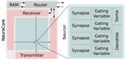
The image is a technical schematic diagram illustrating the high-level architecture of a "NeuroCore" processing unit and its connection to a detailed breakdown of a "Neuron" component. The diagram uses a block-and-line style with color-coded regions to denote different functional areas. It appears to describe a hardware or architectural model for neural network processing.
### Components/Axes
The diagram is divided into two primary sections connected by lines, indicating a hierarchical or compositional relationship.
**Left Section (System Architecture):**
* **Top Block:** Labeled **"Router"**. It has bidirectional arrows connecting to a block labeled **"RAM"** (to its left) and unidirectional arrows pointing downwards to the "NeuroCore" block.
* **Main Block:** A large pink rectangle labeled **"NeuroCore"** on its left edge.
* Inside the NeuroCore, a smaller light-blue square is centered.
* The top area of the NeuroCore (above the blue square) is labeled **"Receiver"**.
* The bottom area of the NeuroCore (below the blue square) is labeled **"Transmitter"**.
* A central point within the blue square has four arrows radiating outwards (up, down, left, right), connecting to the boundaries of the NeuroCore block.
**Right Section (Neuron Detail):**
* A large, light-gray rectangle is labeled **"Neuron"** vertically along its left edge.
* This rectangle is subdivided into a 4x3 grid (four rows, three columns).
* **Column Headers (from left to right):**
1. **"Synapse"** (This label appears in all four rows of the first column).
2. **"Gating Variable"** (This label appears in all four rows of the second column).
3. The third column is split vertically:
* The top two rows are grouped under the label **"Soma"**.
* The bottom two rows are grouped under the label **"Dendrite"**.
**Connections:**
* Two diagonal lines connect the central point of the NeuroCore's blue square to the top-left and bottom-left corners of the "Neuron" block, indicating that the NeuroCore's central processing element is composed of or interfaces with these Neuron components.
### Detailed Analysis
**Spatial Layout and Flow:**
1. **Data Flow Path:** The primary data flow appears to be: **RAM ↔ Router → NeuroCore**. The Router acts as an intermediary between memory (RAM) and the processing core.
2. **NeuroCore Internal Structure:** The NeuroCore has dedicated "Receiver" and "Transmitter" sections, suggesting a clear separation for input and output data handling. The central point with radiating arrows implies a central processing or distribution hub within the core.
3. **Neuron Component Hierarchy:** The "Neuron" is not a monolithic block but is decomposed into fundamental computational elements:
* **Synapse:** Likely represents the connection weight or interface point. It is the first component in the processing chain for each sub-unit.
* **Gating Variable:** Positioned after the Synapse, this likely controls signal flow or modulation, analogous to gating mechanisms in biological neurons or artificial gating units (e.g., in LSTMs).
* **Soma & Dendrite:** These are grouped separately. The "Soma" (cell body) typically integrates signals, while "Dendrites" receive signals. Their placement in the final column suggests they are the output or integration stages of the neuron model. The split indicates two distinct types of integration or output pathways within a single neuron unit.
**Text Transcription (All text is in English):**
* RAM
* Router
* NeuroCore
* Receiver
* Transmitter
* Neuron
* Synapse (x4)
* Gating Variable (x4)
* Soma
* Dendrite
### Key Observations
1. **Modular Design:** The architecture emphasizes modularity, with a clear separation between system-level components (Router, RAM, NeuroCore) and the detailed internal structure of the basic computational unit (Neuron).
2. **Hierarchical Abstraction:** The diagram uses a "zoom-in" technique. The NeuroCore is shown as a black box at the system level, but its connection to the detailed Neuron diagram reveals its internal composition.
3. **Symmetry in Neuron Layout:** The Neuron block is perfectly symmetrical with four identical rows of "Synapse" and "Gating Variable," suggesting a parallel or multi-channel processing design within a single neuron. The differentiation only occurs at the final stage (Soma vs. Dendrite).
4. **Color Coding:** Pink is used for the NeuroCore boundary, light blue for its internal processing area, and light gray for the Neuron detail. This visually separates the different levels of abstraction.
### Interpretation
This diagram outlines a **neuromorphic computing architecture** or a specialized **neural processing unit (NPU)** design. It bridges the gap between high-level system interconnects and low-level neuronal computation.
* **What it demonstrates:** The design prioritizes efficient data movement (via the Router) and massively parallel, fine-grained neural computation. The decomposition of a "Neuron" into Synapse, Gating Variable, Soma, and Dendrite suggests a biologically inspired, yet hardware-optimized model. The four parallel rows within the Neuron could represent multiple input channels, dendritic branches, or parallel processing pathways that are integrated at the Soma/Dendrite stage.
* **Relationships:** The Router is the traffic controller, managing data between memory and compute. The NeuroCore is the compute engine, which itself is built from an array of Neuron units. Each Neuron unit is a complex sub-processor with its own internal stages for synaptic input, gating, and somatic/dendritic integration.
* **Notable Implications:** The explicit inclusion of a "Gating Variable" is significant. It indicates the hardware natively supports dynamic control of signal propagation, which is crucial for implementing advanced neural network models like those with attention mechanisms or recurrent networks with forget gates. This is not just a simple matrix multiplier but a more sophisticated, programmable neural element. The separation of Soma and Dendrite pathways might allow for different computational models (e.g., standard integrate-and-fire vs. more complex dendritic computation) to be implemented on the same hardware.