## Line Graphs: ACC and ECE Performance Across Layers
### Overview
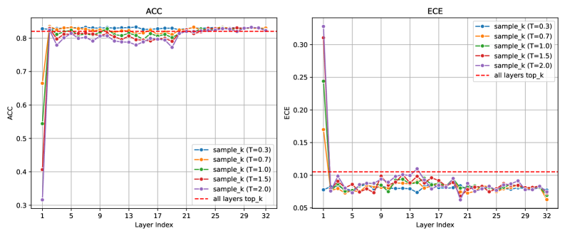
The image contains two line graphs comparing the performance of different sampling strategies (sample_k with varying temperature T values) across 32 layers. The left graph measures **ACC** (Accuracy), while the right graph measures **ECE** (Expected Calibration Error). A dashed red line labeled "all layers top_k" serves as a reference benchmark in both graphs.
---
### Components/Axes
#### ACC Graph (Left)
- **X-axis**: Layer Index (1 to 32, integer increments).
- **Y-axis**: ACC (0.3 to 0.8, increments of 0.1).
- **Legend**:
- Blue: sample_k (T=0.3)
- Orange: sample_k (T=0.7)
- Green: sample_k (T=1.0)
- Red: sample_k (T=1.5)
- Purple: sample_k (T=2.0)
- Dashed Red: all layers top_k
#### ECE Graph (Right)
- **X-axis**: Layer Index (1 to 32, integer increments).
- **Y-axis**: ECE (0.05 to 0.3, increments of 0.05).
- **Legend**: Same color coding as ACC graph.
---
### Detailed Analysis
#### ACC Graph
- **Initial Drop**: All lines (sample_k T values) start near 0.3 at Layer 1, then sharply rise to ~0.8 by Layer 5.
- **Stabilization**: After Layer 5, all lines plateau at ~0.8, matching the dashed red benchmark.
- **T Value Behavior**:
- T=0.3 (blue) and T=0.7 (orange) show the steepest initial rise.
- T=2.0 (purple) has the slowest ascent but converges by Layer 5.
- **Dashed Line**: Constant at 0.8, suggesting a theoretical maximum ACC.
#### ECE Graph
- **Initial Drop**: All lines start near 0.3 at Layer 1, then sharply decline to ~0.05–0.10 by Layer 5.
- **Fluctuation**: After Layer 5, lines oscillate between 0.05 and 0.15, with no clear convergence.
- **T Value Behavior**:
- T=0.3 (blue) and T=0.7 (orange) show the most volatility post-Layer 5.
- T=2.0 (purple) exhibits the smoothest fluctuations.
- **Dashed Line**: Constant at 0.10, acting as a baseline for comparison.
---
### Key Observations
1. **ACC Convergence**: All sampling strategies achieve near-identical accuracy (~0.8) after Layer 5, regardless of T value.
2. **ECE Divergence**: While ECE stabilizes post-Layer 5, performance varies by T value, with T=2.0 showing the least error.
3. **Dashed Line Significance**: The "all layers top_k" benchmark (0.8 ACC / 0.10 ECE) suggests an ideal or average performance threshold.
4. **Layer 1 Anomaly**: All metrics start at suboptimal values (ACC ~0.3, ECE ~0.3), indicating poor initial layer performance.
---
### Interpretation
- **ACC**: The rapid convergence to 0.8 implies that layer depth (beyond Layer 5) has minimal impact on accuracy, and T values do not significantly affect long-term performance.
- **ECE**: The lack of convergence in ECE suggests that calibration error remains sensitive to T values and layer interactions, even after initial stabilization.
- **Dashed Line as Benchmark**: The constant dashed line may represent an optimal or average performance target, with most strategies falling short in ECE but meeting ACC goals.
- **Practical Implications**: While accuracy is robust across layers and T values, calibration error highlights the need for careful temperature tuning in later layers to minimize uncertainty.