TECHNICAL ASSET FINGERPRINT
56d69ccc192b90c3b93e5e28
Click to view fullscreen
Press ESC or click to close
FOUND IN PAPERS
EXPERT: healer-alpha-free VERSION 1
RUNTIME: free/openrouter/healer-alpha
INTEL_VERIFIED
## Diagram: Transformer Architecture (Encoder-Decoder)
### Overview
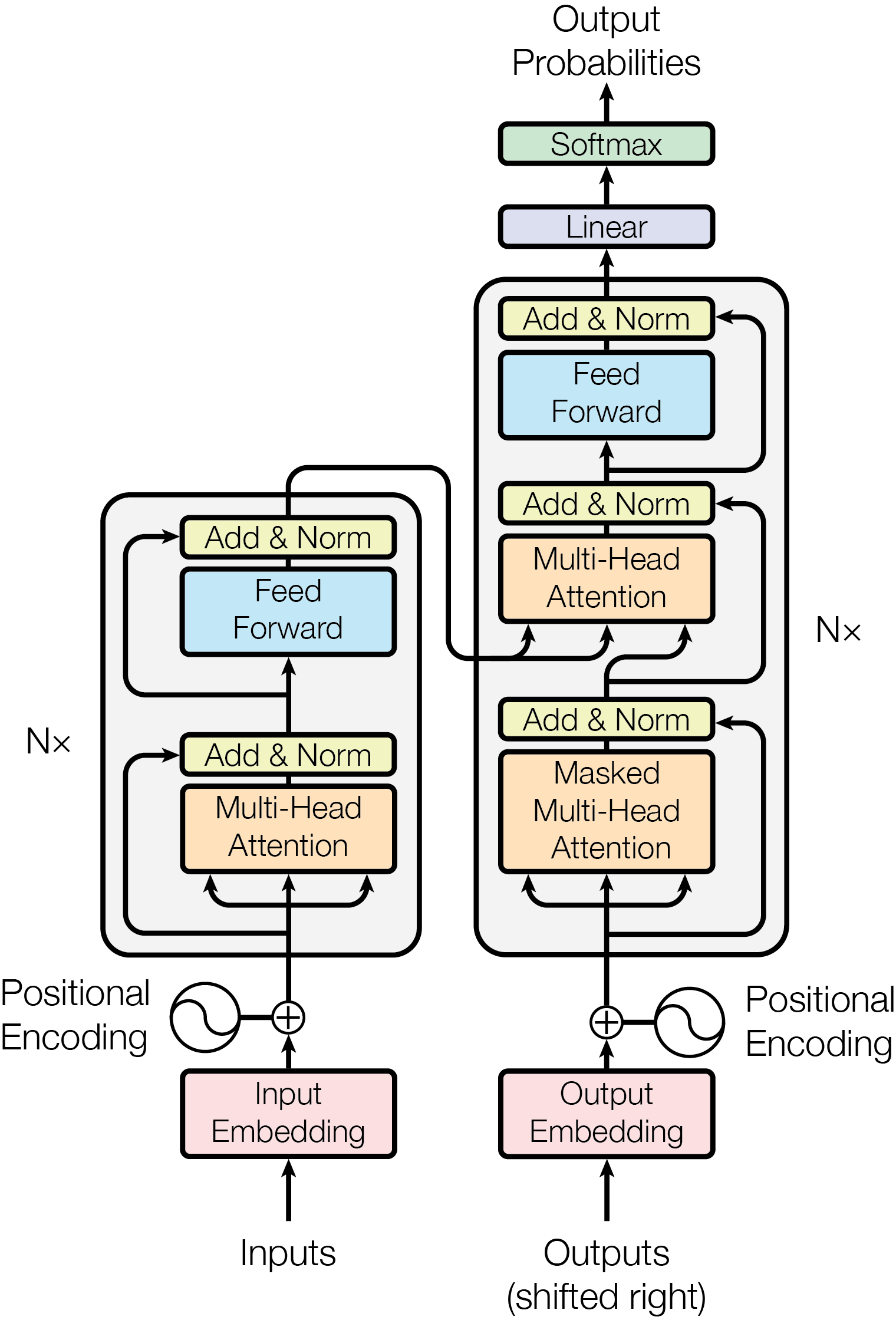
This image is a technical schematic diagram illustrating the architecture of the Transformer model, a neural network architecture primarily used for sequence-to-sequence tasks like machine translation. The diagram is presented in a vertical, flowchart-style layout on a light gray background. It clearly separates the model into two main stacks: an **Encoder** on the left and a **Decoder** on the right, which are connected. The flow of data is from the bottom (Inputs/Outputs) to the top (Output Probabilities).
### Components/Axes
The diagram is composed of labeled rectangular blocks, circles, and directional arrows indicating data flow. There are no traditional chart axes. The key components and their spatial relationships are:
**1. Input Pathway (Bottom-Left):**
* **Inputs**: Text label at the very bottom left.
* **Input Embedding**: A pink rectangular block directly above "Inputs".
* **Positional Encoding**: A circular icon with a sine wave symbol, located to the left of the Input Embedding block. An arrow points from this circle to a summation symbol (`+`) above the Input Embedding.
* **Summation (`+`)**: A circle with a plus sign, indicating the addition of the Input Embedding and Positional Encoding.
**2. Encoder Stack (Left, labeled "Nx"):**
* A large rounded rectangle enclosing a repeating block (indicated by "Nx" to its left).
* **Multi-Head Attention**: An orange rectangular block. It receives three arrows from below (representing Queries, Keys, Values).
* **Add & Norm**: A yellow rectangular block directly above the Multi-Head Attention block. A residual connection (curved arrow) bypasses the Multi-Head Attention and Add & Norm blocks, feeding into the Add & Norm block.
* **Feed Forward**: A light blue rectangular block above the first Add & Norm.
* **Add & Norm**: A second yellow rectangular block above the Feed Forward block. Another residual connection bypasses the Feed Forward and this Add & Norm block.
* The output of this entire Encoder block is fed into the Decoder stack.
**3. Decoder Stack (Right, labeled "Nx"):**
* A larger rounded rectangle enclosing a repeating block (indicated by "Nx" to its right).
* **Masked Multi-Head Attention**: An orange rectangular block at the bottom of the decoder stack. It receives arrows from below.
* **Add & Norm**: A yellow rectangular block above the Masked Multi-Head Attention. A residual connection bypasses both.
* **Multi-Head Attention**: A second orange rectangular block. This block receives two sets of inputs: one from the Add & Norm block below it, and another from the output of the Encoder stack (indicated by a long arrow coming from the left).
* **Add & Norm**: A yellow rectangular block above this Multi-Head Attention. A residual connection bypasses it.
* **Feed Forward**: A light blue rectangular block.
* **Add & Norm**: The final yellow rectangular block at the top of the decoder stack. A residual connection bypasses the Feed Forward and this block.
**4. Output Pathway (Bottom-Right to Top):**
* **Outputs (shifted right)**: Text label at the very bottom right.
* **Output Embedding**: A pink rectangular block above the "Outputs" label.
* **Positional Encoding**: A circular icon with a sine wave symbol, located to the right of the Output Embedding. An arrow points to a summation symbol (`+`).
* **Summation (`+`)**: Adds the Output Embedding and Positional Encoding.
* The result is fed into the bottom of the Decoder stack.
* **Linear**: A light purple rectangular block above the Decoder stack.
* **Softmax**: A light green rectangular block above the Linear block.
* **Output Probabilities**: Text label at the very top, with an arrow pointing up from the Softmax block.
### Detailed Analysis
The diagram meticulously details the data flow and internal operations of the Transformer:
* **Flow Direction**: The process is strictly bottom-up. Data enters at the bottom ("Inputs" and "Outputs (shifted right)"), passes through embedding and positional encoding layers, then through multiple identical encoder/decoder layers (Nx times), and finally through a linear and softmax layer to produce output probabilities at the top.
* **Encoder-Decoder Connection**: A critical connection is shown by a long, curved arrow originating from the output of the Encoder stack (left) and feeding into the **Multi-Head Attention** block within the Decoder stack (right). This is how the decoder accesses the encoded representation of the input sequence.
* **Residual Connections**: Every major sub-layer (Multi-Head Attention, Feed Forward) is followed by an "Add & Norm" block. The diagram shows this with a primary arrow going into the sub-layer and a parallel, curved "residual" arrow that bypasses the sub-layer and connects directly to the "Add & Norm" block. This visualizes the residual connection and layer normalization step.
* **Masking**: The first attention block in the decoder is specifically labeled **"Masked"** Multi-Head Attention, indicating it prevents positions from attending to subsequent positions, preserving the auto-regressive property.
* **Repetition**: The "Nx" labels next to the encoder and decoder stacks signify that the entire block within the rounded rectangle is repeated N times (a hyperparameter).
### Key Observations
1. **Symmetry and Asymmetry**: The encoder and decoder stacks are structurally similar (both have attention and feed-forward sub-layers with residual connections) but not identical. The decoder has an additional cross-attention layer and uses masking in its first attention layer.
2. **Color Coding**: Components are consistently color-coded:
* Pink: Embedding layers.
* Orange: Attention mechanisms (Multi-Head, Masked Multi-Head).
* Light Blue: Feed Forward networks.
* Yellow: Add & Norm (Residual connection + Layer Normalization).
* Light Purple: Linear transformation.
* Light Green: Softmax activation.
3. **Positional Encoding**: Represented by identical sine wave icons added to both input and output embeddings, emphasizing that the model requires explicit information about token position, as it contains no recurrence or convolution.
4. **Data Flow Clarity**: The arrows are unambiguous. For example, the three arrows into each Multi-Head Attention block clearly represent the Query (Q), Key (K), and Value (V) inputs.
### Interpretation
This diagram is the foundational blueprint for the Transformer architecture. It visually explains the key innovations that enabled its success:
* **Parallelization**: Unlike recurrent neural networks (RNNs), the encoder and decoder stacks process all input tokens simultaneously via the **Multi-Head Attention** mechanism, allowing for highly parallel computation.
* **Contextual Understanding**: The **Multi-Head Attention** blocks allow the model to weigh the importance of different words in the input sequence when processing a given word, capturing long-range dependencies effectively.
* **Sequence-to-Sequence Mapping**: The architecture is explicitly designed for tasks where an input sequence (e.g., an English sentence) must be transformed into an output sequence (e.g., its French translation). The encoder creates a rich representation of the input, and the decoder generates the output one token at a time, attending to both this encoded representation and the previously generated tokens (via masked self-attention).
* **Modularity and Depth**: The "Nx" repetition indicates the model's depth, which is crucial for learning complex patterns. The clear separation of sub-layers (attention, feed-forward, normalization) makes the architecture modular and easier to analyze and scale.
The diagram is not a data chart but a precise technical schematic. It contains no numerical data or trends but provides complete structural information about one of the most influential models in modern machine learning.
DECODING INTELLIGENCE...