## Logic Gate Diagram: FT Gates Formalization
### Overview
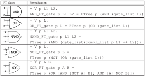
The image presents a table describing several fundamental logic gates (AND, OR, NAND, NOR, XOR) using both their symbolic representation and a formalization using a functional notation. The table is organized into two columns: "FT Gates" showing the gate symbol, and "Formalization" providing the logical expression.
### Components/Axes
* **Table Header:**
* Column 1: "FT Gates" - Contains the logic gate symbols.
* Column 2: "Formalization" - Contains the formal representation of the logic gates.
* **Logic Gates:** The following logic gates are represented: AND, OR, NAND, NOR, XOR.
* **Formalization Notation:** The formalization uses symbols like ∀ (for all), p, L, L1, L2, A, B, FTree, AND, OR, NOT, gate_list, compl_list, ++.
### Detailed Analysis
The table consists of 5 rows, each representing a different logic gate.
* **AND Gate:**
* Symbol: Standard AND gate symbol with 'n' inputs indicated by dashed lines. Inputs are labeled '1' and 'n'.
* Formalization: "∀ p L1 L2. AND\_FT\_gate p L1 L2 = FTree p (AND (gate\_list L))"
* **OR Gate:**
* Symbol: Standard OR gate symbol with 'n' inputs indicated by dashed lines. Inputs are labeled '1' and 'n'.
* Formalization: "∀ p L. OR\_FT\_gate p L = FTree p (OR (gate\_list L))"
* **NAND Gate:**
* Symbol: Standard NAND gate symbol with 'k' inputs indicated by dashed lines. Inputs are labeled '-1' and '-k'.
* Formalization: "∀ p L1 L2. NAND\_FT\_gate p L1 L2 = FTree p (AND (gate\_list (compl\_list p L1 ++ L2)))"
* **NOR Gate:**
* Symbol: Standard NOR gate symbol with 'n' inputs indicated by dashed lines. Input is labeled '-1' and '-n'.
* Formalization: "∀ p L. NOR\_FT\_gate p L = FTree p (NOT (OR (gate\_list L)))"
* **XOR Gate:**
* Symbol: Standard XOR gate symbol with two inputs. Inputs are labeled '-1' and '-2'.
* Formalization: "∀ p A B. XOR\_FT\_gate p A B = FTree p (OR [AND [NOT A; B]; AND [A; NOT B]])"
### Key Observations
* The formalization uses a functional notation to represent the logic gates.
* The number of inputs is explicitly indicated for AND, OR, NAND, and NOR gates, while XOR is shown with two inputs.
* The formalization includes functions like `FTree`, `gate_list`, and `compl_list`, suggesting a tree-based representation or manipulation of gates.
* The NAND gate formalization includes `compl_list`, indicating a complement operation.
* The XOR gate formalization explicitly shows the logical expression (A'B + AB').
### Interpretation
The image provides a formal representation of common logic gates, bridging the gap between their symbolic representation and a functional or algebraic description. This type of formalization is useful in automated reasoning, circuit verification, and logic synthesis. The use of functions like `FTree` and `gate_list` suggests a more abstract or hierarchical representation of logic circuits, potentially used in formal verification or synthesis tools. The formalization allows for a precise and unambiguous definition of each gate's behavior, which is essential for automated manipulation and analysis.