\n
## Table: Formalization of FT Gates
### Overview
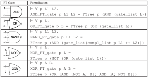
The image presents a table detailing the formalization of fundamental logic gates (AND, OR, NAND, NOR, XOR). Each row corresponds to a specific gate, displaying its symbol, and a corresponding mathematical or logical expression.
### Components/Axes
The table has two columns:
1. **FT Gates:** This column displays the schematic symbol for each logic gate.
2. **Formalization:** This column provides the logical or mathematical expression representing the gate's function.
### Content Details
Here's a detailed transcription of the table's content, row by row:
* **AND:**
* Symbol: Standard AND gate symbol.
* Formalization: `¬ ∀ p L1 L2. AND_FT_gate p L1 L2 = FTree p (AND (gate_list L1))`
* **OR:**
* Symbol: Standard OR gate symbol.
* Formalization: `¬ ∀ p L. OR_FT_gate p L = FTree p (OR (gate_list L))`
* **NAND:**
* Symbol: Standard NAND gate symbol.
* Formalization: `¬ ∀ p L1 L2. NAND_FT_gate p L1 L2 = FTree p (AND (gate_list (compl_list p ++ L2)))`
* **NOR:**
* Symbol: Standard NOR gate symbol.
* Formalization: `¬ ∀ p L. NOR_FT_gate p L = FTree p (NOT (OR (gate_list L)))`
* **XOR:**
* Symbol: Standard XOR gate symbol.
* Formalization: `¬ ∀ p A B. XOR_FT_gate p A B = FTree p (OR [AND [NOT A; B]; AND [A; NOT B]])`
### Key Observations
* The formalizations utilize a notation involving `FTree`, `AND`, `OR`, `NOT`, `compl_list`, and `gate_list`.
* The expressions appear to define the gate's behavior in terms of a tree structure (`FTree`) and operations on lists of inputs (`gate_list`).
* The `compl_list` function in the NAND gate formalization suggests a negation or complement operation on the input list.
* The XOR gate formalization is more complex, involving nested `AND` and `OR` operations with negated inputs.
### Interpretation
This table provides a formal, potentially computational, representation of basic logic gates. The use of `FTree` suggests a hierarchical or tree-based approach to representing the gate's functionality. The expressions are likely intended for use in a system that can manipulate and evaluate these logical structures, perhaps for automated theorem proving, circuit verification, or logic synthesis. The notation is somewhat abstract and requires understanding of the underlying mathematical or logical framework to fully interpret. The use of `¬ ∀` suggests a universal quantification with negation, indicating a rule or definition that holds for all possible inputs. The expressions are not standard Boolean algebra but a more specialized formalization. The table is a technical document aimed at someone familiar with formal logic and potentially functional programming concepts.