## Diagram: State Transition Model with Negation and Expansion
### Overview
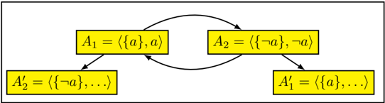
The diagram illustrates a cyclical state transition system involving four labeled components (A₁, A₂, A₁′, A₂′) connected by bidirectional arrows. Each component contains set notation with logical operators (¬ for negation) and ellipses indicating continuation. The structure suggests a feedback loop between two primary states (A₁ and A₂) that evolve into expanded versions (A₁′ and A₂′).
### Components/Axes
1. **Rectangular Nodes**:
- **A₁**: Top-left rectangle labeled `⟨{a}, a⟩` (set containing "a" and element "a").
- **A₂**: Top-right rectangle labeled `⟨{¬a}, ¬a⟩` (set containing negation of "a" and element "¬a").
- **A₁′**: Bottom-right rectangle labeled `⟨{a}, ...⟩` (set starting with "a" followed by unspecified elements).
- **A₂′**: Bottom-left rectangle labeled `⟨{¬a}, ...⟩` (set starting with "¬a" followed by unspecified elements).
2. **Arrows**:
- **A₁ → A₂**: Direct transition between negation states.
- **A₂ → A₁′**: Transition from negated state to expanded "a" state.
- **A₁′ → A₂′**: Transition between expanded states.
- **A₂′ → A₁**: Closing the loop back to the original negation state.
### Detailed Analysis
- **Notation**: The use of angle brackets (`⟨...⟩`) suggests ordered pairs or tuples, while set notation (`{...}`) implies membership or state composition.
- **Negation**: The presence of `¬a` in A₂ and A₂′ indicates logical inversion of the base element "a".
- **Ellipses**: The `...` in A₁′ and A₂′ imply additional, unspecified elements in the expanded states, suggesting growth or complexity beyond the initial states.
### Key Observations
1. **Cyclical Dependency**: The loop between A₁ and A₂ creates a binary toggle between "a" and "¬a" states.
2. **State Expansion**: Transitions to A₁′ and A₂′ introduce new elements, indicating a progression from simple to complex states.
3. **Symmetry**: The diagram balances negation (`¬a`) and affirmation (`a`) across the cycle, with mirrored structures in A₁/A₂ and A₁′/A₂′.
### Interpretation
This diagram likely represents a **state machine** or **logical process** where:
- **A₁ and A₂** are foundational states governed by mutual exclusion (one active, the other negated).
- **A₁′ and A₂′** represent evolved states where the original element ("a" or "¬a") is retained but expanded with additional components, possibly reflecting iterative processes or compounded conditions.
- The cyclical arrow from A₂′ back to A₁ suggests a reset or reinitialization mechanism, enabling repeated application of the state transitions.
The model could apply to systems requiring alternating conditions (e.g., binary logic gates, decision trees) or processes with feedback loops (e.g., iterative algorithms, reinforcement learning). The ellipses hint at scalability, where the system can accommodate additional rules or variables beyond the initial states.