# Technical Document Extraction: System Phase Diagram
## Diagram Overview
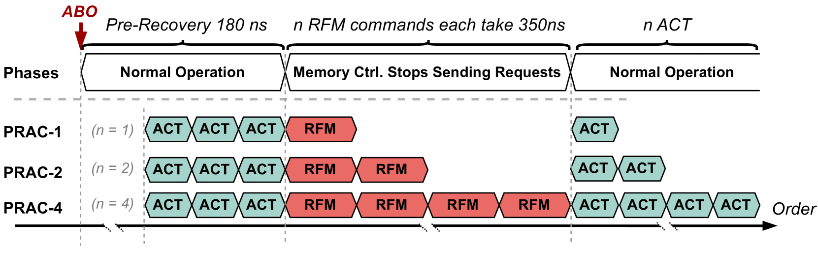
The image depicts a **timeline-based system phase diagram** illustrating memory controller behavior across three operational phases. The diagram uses color-coded hexagonal blocks to represent command sequences and includes temporal annotations.
---
## Key Components & Labels
### Axes
- **X-axis (Phases)**:
- Labeled "Phases" with three distinct sections:
1. **Normal Operation** (left)
2. **Memory Ctrl. Stops Sending Requests** (center)
3. **Normal Operation** (right)
- Dashed vertical lines separate phases.
- **Y-axis (PRAC Levels)**:
- Three levels labeled:
- PRAC-1 (n = 1)
- PRAC-2 (n = 2)
- PRAC-4 (n = 4)
- Positioned from top to bottom.
### Legend
- **Color Coding**:
- **Green (#4ECDC4)**: `ACT` commands
- **Red (#FF4500)**: `RFM` commands
- Located at the top of the diagram.
---
## Temporal Annotations
1. **Pre-Recovery Phase**:
- Marked with a red arrow labeled `ABO`.
- Duration: **180 ns** (noted above the first phase).
2. **RFM Command Timing**:
- Each `RFM` command takes **350 ns** (noted above the second phase).
3. **ACT Command Timing**:
- `ACT` commands are unlabeled but implied to occur in the first and third phases.
---
## Command Sequences by PRAC Level
### PRAC-1 (n = 1)
- **Phase 1 (Normal Operation)**:
- 3 `ACT` commands (green blocks).
- **Phase 2 (Memory Ctrl. Stops Sending Requests)**:
- 1 `RFM` command (red block).
- **Phase 3 (Normal Operation)**:
- 1 `ACT` command (green block).
### PRAC-2 (n = 2)
- **Phase 1**:
- 3 `ACT` commands.
- **Phase 2**:
- 2 `RFM` commands.
- **Phase 3**:
- 2 `ACT` commands.
### PRAC-4 (n = 4)
- **Phase 1**:
- 3 `ACT` commands.
- **Phase 2**:
- 4 `RFM` commands.
- **Phase 3**:
- 4 `ACT` commands.
---
## Key Trends
1. **RFM Command Scaling**:
- Number of `RFM` commands increases linearly with PRAC level (`n`):
- PRAC-1: 1 `RFM`
- PRAC-2: 2 `RFM`
- PRAC-4: 4 `RFM`
2. **ACT Command Consistency**:
- `ACT` commands remain constant at **3** during the first phase across all PRAC levels.
- Post-Memory Ctrl., `ACT` commands match the PRAC level (`n`):
- PRAC-1: 1 `ACT`
- PRAC-2: 2 `ACT`
- PRAC-4: 4 `ACT`
3. **Phase Transitions**:
- The Memory Ctrl. phase introduces `RFM` commands, which are absent in the initial Normal Operation phase.
- After the Memory Ctrl. phase, the system resumes `ACT` commands in the final Normal Operation phase.
---
## Spatial Grounding
- **Legend Position**: Top-center (x = 0.5, y = 1.0 in diagram coordinates).
- **PRAC Level Order**: Top-to-bottom (PRAC-1 > PRAC-2 > PRAC-4).
- **Phase Boundaries**: Dashed vertical lines at x = 0.3 and x = 0.7.
---
## Data Table Reconstruction
| PRAC Level | Phase 1 (ACT) | Phase 2 (RFM) | Phase 3 (ACT) |
|------------|---------------|---------------|---------------|
| PRAC-1 | 3 | 1 | 1 |
| PRAC-2 | 3 | 2 | 2 |
| PRAC-4 | 3 | 4 | 4 |
---
## Notes
- **No Other Languages Detected**: All text is in English.
- **Critical Annotation**: The `ABO` label (red arrow) indicates a system-wide pre-recovery event preceding Phase 1.
- **Temporal Constraints**: RFM commands are explicitly timed at 350 ns, while ACT command durations are unspecified but implied to be shorter (given their placement in Normal Operation phases).
This diagram illustrates a memory controller's response to abnormal conditions (ABO), with PRAC levels determining the number of RFM commands issued during error recovery.