## Timing Diagram: Bank Access with RFM
### Overview
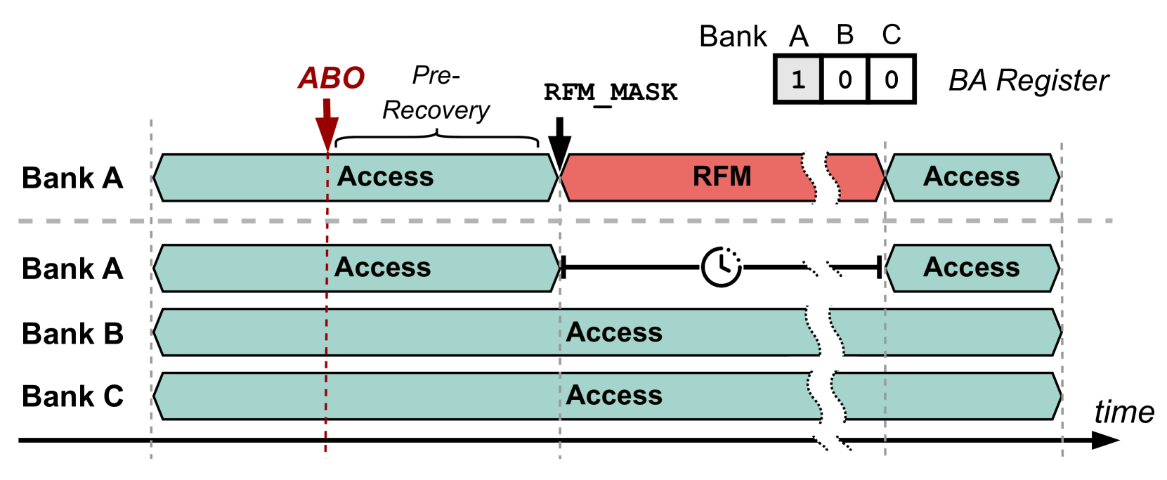
The image is a timing diagram illustrating memory bank access sequences, including a Read-For-Modify (RFM) operation. It shows the timing relationships between accesses to different memory banks (Bank A, Bank B, Bank C) and the RFM operation on Bank A. The diagram also indicates the "Pre-Recovery" period and the "ABO" point.
### Components/Axes
* **Vertical Axis:** Represents different memory banks: Bank A (appears twice), Bank B, and Bank C.
* **Horizontal Axis:** Represents time, indicated by an arrow labeled "time" pointing to the right.
* **Access Blocks:** Teal colored blocks represent memory access operations.
* **RFM Block:** A red colored block represents the Read-For-Modify operation.
* **ABO:** A red arrow pointing down, labeled "ABO".
* **RFM\_MASK:** A black arrow pointing down, labeled "RFM\_MASK".
* **Pre-Recovery:** A label indicating the period between ABO and RFM\_MASK.
* **BA Register:** A table showing the bank address register values for banks A, B, and C. The values are 1, 0, and 0 respectively.
* **Clock Icon:** A clock icon is present between the two Bank A access sequences.
* **Dashed Lines:** Vertical dashed lines indicate specific time points. Horizontal dashed lines separate the two Bank A rows.
### Detailed Analysis
* **Bank A (Top):**
* Starts with an "Access" operation (teal).
* A red arrow labeled "ABO" points down at the end of the "Access" block.
* The region between "ABO" and the start of the "RFM" block is labeled "Pre-Recovery".
* A black arrow labeled "RFM\_MASK" points down at the start of the "RFM" block.
* The "RFM" operation (red) follows.
* Ends with another "Access" operation (teal).
* Trend: Access -> ABO -> Pre-Recovery -> RFM\_MASK -> RFM -> Access
* **Bank A (Middle):**
* Starts with an "Access" operation (teal).
* A horizontal line extends from the end of the "Access" block to a clock icon.
* Ends with another "Access" operation (teal).
* Trend: Access -> Delay (Clock) -> Access
* **Bank B:**
* Starts with an "Access" operation (teal).
* Ends with another "Access" operation (teal).
* Trend: Access -> Access
* **Bank C:**
* Starts with an "Access" operation (teal).
* Ends with another "Access" operation (teal).
* Trend: Access -> Access
* **BA Register:**
* Bank A: 1
* Bank B: 0
* Bank C: 0
### Key Observations
* Bank A undergoes an RFM operation after an initial access.
* The "Pre-Recovery" period is the time between the "ABO" point and the "RFM\_MASK" point.
* The second Bank A access is delayed, as indicated by the clock icon.
* Banks B and C have simple access operations without RFM.
* The BA Register shows that Bank A is selected (1), while Banks B and C are not (0).
### Interpretation
The diagram illustrates a scenario where Bank A requires a Read-For-Modify operation. The "ABO" point likely signifies a specific event or signal related to the access. The "Pre-Recovery" period might be a time needed for internal operations before the RFM can be initiated. The "RFM\_MASK" likely indicates when the RFM operation is masked or enabled. The delay in the second Bank A access could be due to the RFM operation or other internal processes. The BA Register confirms that Bank A is the target of the RFM operation. The diagram highlights the timing dependencies and sequence of operations involved in accessing and modifying data in Bank A, while Banks B and C undergo standard access operations.