## System Architecture Diagram: Before and After MCP (Model Context Protocol)
### Overview
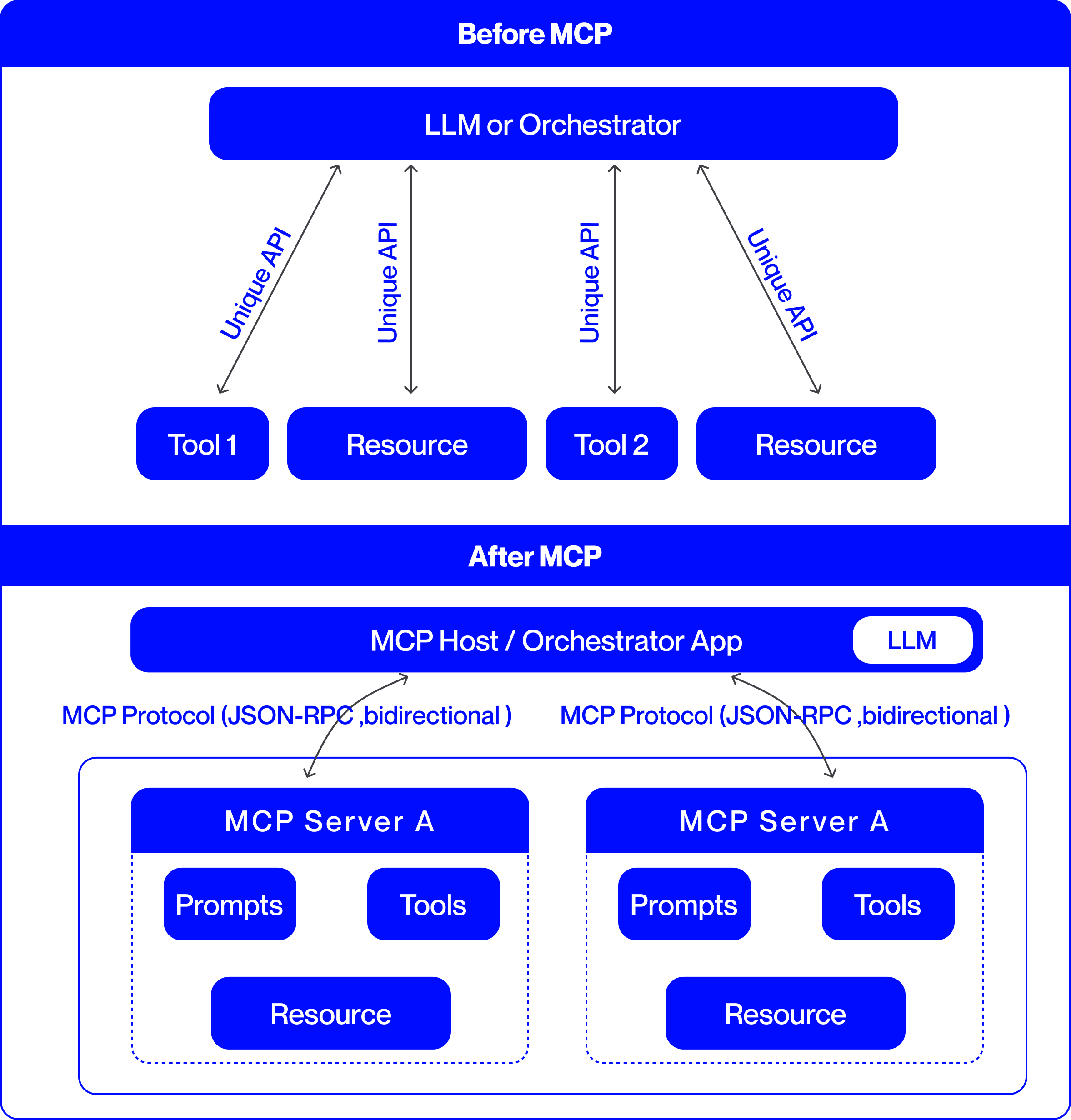
This image is a technical comparison diagram illustrating two different architectural approaches for integrating Large Language Models (LLMs) with external tools and resources. The top half is labeled "Before MCP," showing a point-to-point integration model. The bottom half is labeled "After MCP," demonstrating a standardized, protocol-based integration model using the Model Context Protocol (MCP). The diagram uses a consistent color scheme: blue boxes for components and black arrows for connections, set against a light gray background.
### Components/Axes
The diagram is divided into two primary horizontal sections, each with a distinct architecture.
**1. "Before MCP" Section (Top Half):**
* **Central Component:** A large blue rounded rectangle at the top labeled **"LLM or Orchestrator"**.
* **Peripheral Components:** Four smaller blue rounded rectangles arranged horizontally below the central component. From left to right, they are labeled:
* **"Tool 1"**
* **"Resource"**
* **"Tool 2"**
* **"Resource"**
* **Connections:** Four separate, double-headed arrows connect the central "LLM or Orchestrator" to each of the four peripheral components. Each arrow is labeled with the text **"Unique API"**, indicating a custom, point-to-point integration for each tool and resource.
**2. "After MCP" Section (Bottom Half):**
* **Central Component:** A large blue rounded rectangle labeled **"MCP Host / Orchestrator App"**. Embedded within its right side is a smaller white rounded rectangle labeled **"LLM"**.
* **Protocol Layer:** Two curved, double-headed arrows originate from the bottom of the "MCP Host" component. Each arrow is labeled with the text **"MCP Protocol (JSON-RPC, bidirectional)"**.
* **Server Components:** The arrows point to two identical, large blue-outlined containers, each representing an **"MCP Server A"**. The label "MCP Server A" appears in the blue header of each container.
* **Internal Server Components:** Within each "MCP Server A" container, there are three blue rounded rectangles:
* **"Prompts"** (top-left)
* **"Tools"** (top-right)
* **"Resource"** (bottom-center)
### Detailed Analysis
The diagram presents a clear before-and-after narrative focused on system integration complexity.
**"Before MCP" Architecture:**
* **Structure:** A hub-and-spoke model with the "LLM or Orchestrator" at the center.
* **Integration Method:** Each external component (Tool 1, Tool 2, and two Resources) requires a dedicated, custom API connection to the central orchestrator. This is explicitly stated by the four instances of the "Unique API" label.
* **Implication:** This model suggests high maintenance overhead, as each new tool or resource requires building and maintaining a bespoke integration.
**"After MCP" Architecture:**
* **Structure:** A layered, protocol-based model. The "MCP Host / Orchestrator App" (which contains the LLM) acts as a client.
* **Integration Method:** Communication is standardized via the **"MCP Protocol"**, specified as using **JSON-RPC** and being **bidirectional**. This single protocol replaces the multiple "Unique API" connections.
* **Server Abstraction:** Tools, prompts, and resources are now encapsulated within standardized **"MCP Server"** containers (exemplified by "MCP Server A"). The diagram shows two identical servers, implying the architecture supports multiple, interoperable servers.
* **Component Grouping:** Within each server, the diagram groups three key element types: **"Prompts"**, **"Tools"**, and **"Resource"**. This indicates that an MCP server can expose a bundle of related capabilities.
### Key Observations
1. **Standardization vs. Customization:** The most prominent shift is from multiple "Unique API" connections to a single, standardized "MCP Protocol."
2. **Encapsulation:** In the "After" model, tools and resources are no longer standalone entities connected directly to the host. They are encapsulated within "MCP Server" units, which also include "Prompts."
3. **Bidirectional Communication:** The "After" diagram explicitly notes the protocol is "bidirectional," suggesting more interactive communication compared to the implied request-response nature of the "Unique API" arrows.
4. **Scalability Hint:** The presence of two identical "MCP Server A" boxes visually suggests that adding new capabilities involves deploying another standard server, rather than building a new custom API.
### Interpretation
This diagram argues for the adoption of the Model Context Protocol (MCP) as a superior architectural pattern for connecting LLMs to the external world.
* **Problem Demonstrated ("Before"):** The "Before MCP" state represents a fragile and non-scalable integration landscape. Each tool or data source ("Resource") requires custom engineering work ("Unique API"), leading to a combinatorial explosion of connections as the ecosystem grows. This creates maintenance burdens and vendor lock-in.
* **Solution Proposed ("After"):** MCP introduces a standardized interface layer. The "MCP Host" (e.g., an AI application) only needs to implement the MCP client protocol once. Any tool or data source that implements the corresponding MCP server protocol can then connect seamlessly. This decouples the host from the specifics of individual tools.
* **Architectural Benefit:** The model promotes **interoperability** and **modularity**. Developers can create "MCP Servers" that expose specific sets of "Tools," "Prompts," and "Resources." These servers can be developed independently and plugged into any MCP-compatible host. This is analogous to how USB standardized connections for computer peripherals, replacing a multitude of proprietary ports.
* **Underlying Principle:** The diagram illustrates a move from **point-to-point integration** to a **networked protocol-based ecosystem**. This is a common evolution in software architecture to manage complexity and foster innovation, allowing tool creators and application developers to work independently against a shared standard.