## Scientific Diagram: Magnetic Layer Structure and Current-Induced Magnetization Dynamics
### Overview
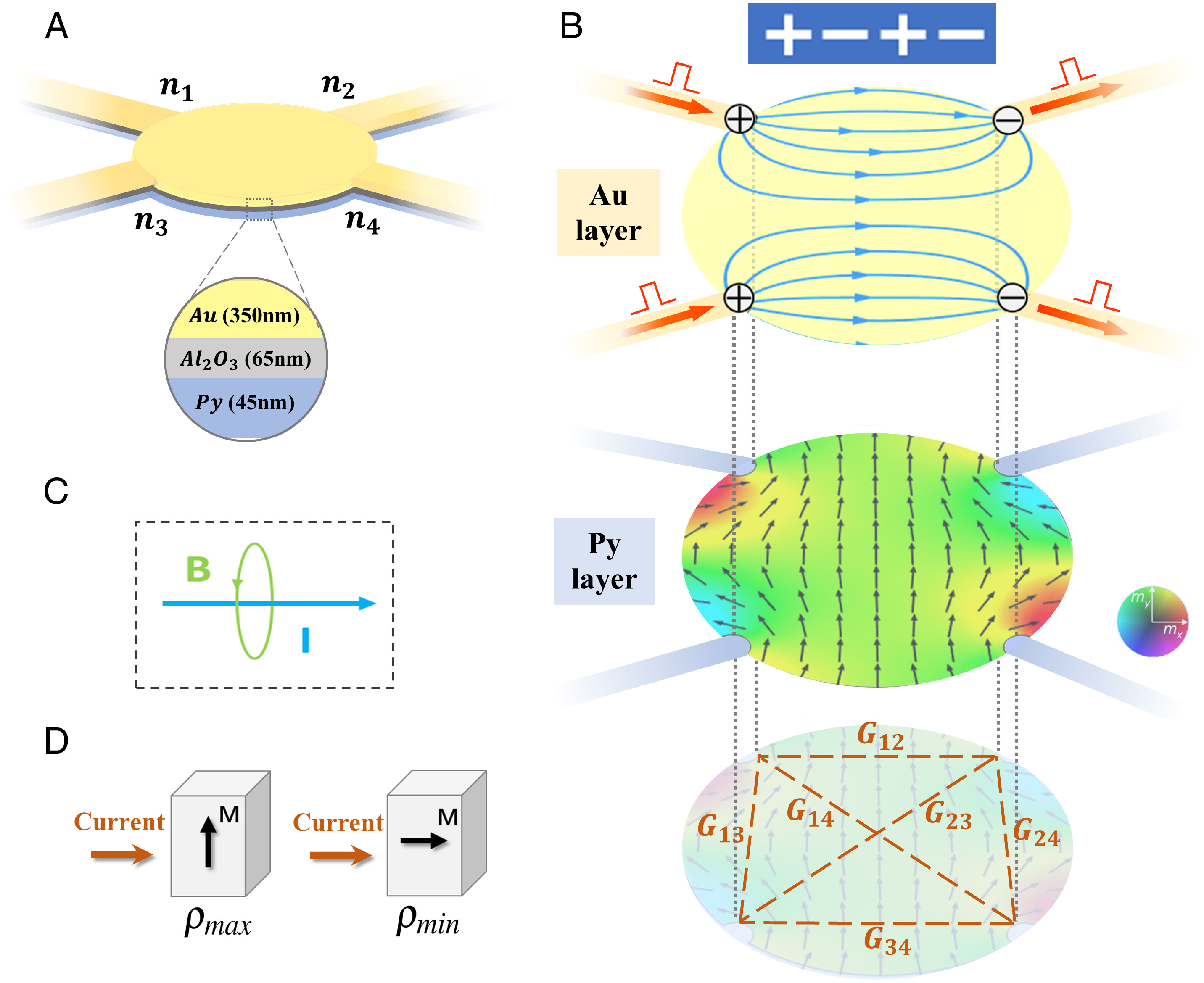
The diagram illustrates a multi-layered magnetic structure with current-induced magnetization dynamics. It comprises four labeled sections (A-D) depicting material layers, current flow, magnetic field interactions, and resistivity states. Key elements include material thickness annotations, directional arrows, and coupling constants.
### Components/Axes
**Section A (Layered Structure):**
- Central yellow circle with four arms labeled **n₁–n₄** (likely current paths or magnetic anisotropy directions).
- Inset cross-section showing:
- **Au (350nm)** – Gold layer
- **Al₂O₃ (65nm)** – Aluminum oxide barrier
- **Py (45nm)** – Ferromagnetic yttrium iron garnet layer
**Section B (Magnetic Interactions):**
- **Au layer** with blue circular arrows (current loops) and red arrows (current direction).
- **Py layer** with:
- Green gradient arrows (magnetization direction)
- Color wheel inset labeled **mₓ** (horizontal magnetization) and **mᵧ** (vertical magnetization)
- Mesh of dashed red lines labeled **G₁₂, G₁₃, G₁₄, G₂₃, G₂₄, G₃₄** (likely coupling constants between nodes)
**Section C (Vector Diagram):**
- Dashed box containing:
- Green circular arrow labeled **B** (magnetic field)
- Blue arrow labeled **I** (current)
**Section D (Resistivity States):**
- Two cubes labeled:
- **ρ_max** (high resistivity state) with upward magnetization (**M↑**)
- **ρ_min** (low resistivity state) with rightward magnetization (**M→**)
### Detailed Analysis
**Section A:**
- Material thicknesses: Au (350nm), Al₂O₃ (65nm), Py (45nm). The Al₂O₃ barrier suggests a magnetic tunnel junction (MTJ) structure.
- Arm labels **n₁–n₄** may represent current injection paths or magnetic easy axes.
**Section B:**
- Blue arrows in Au layer indicate current loops (possibly spin-orbit torque).
- Red arrows point toward Au layer, suggesting current injection direction.
- Py layer's green gradient arrows show magnetization direction, with color intensity correlating to **mₓ** (horizontal) and **mᵧ** (vertical) components.
- Coupling constants **G₁₂–G₃₄** form a mesh, likely representing exchange interactions or spin-wave coupling between nodes.
**Section C:**
- **B** (magnetic field) and **I** (current) vectors are orthogonal, consistent with spin Hall effect or spin-orbit torque mechanisms.
**Section D:**
- **ρ_max** and **ρ_min** correspond to parallel/antiparallel magnetization states in an MTJ, with **M** direction determining resistivity.
### Key Observations
1. The Py layer's color gradient (green → red) in Section B suggests spatially varying magnetization direction, possibly due to current-induced domain wall motion.
2. Coupling constants **G₁₂–G₃₄** form a complete graph, indicating strong inter-node interactions in the Py layer.
3. Section D's resistivity states align with typical MTJ behavior, where magnetization orientation controls resistance.
### Interpretation
This diagram models a spintronic device where current-driven magnetization switching occurs via spin-orbit torque. The layered structure (A) forms an MTJ, with Py as the free layer. Current flow (B, D) generates spin currents that interact with the Py layer's magnetization (B), creating domain wall motion or domain rotation. The coupling constants (G₁₂–G₃₄) likely govern the efficiency of spin-wave propagation or domain wall dynamics. The resistivity states (D) demonstrate how magnetization orientation modulates device resistance, critical for applications like MRAM or logic-in-memory systems. The orthogonal **B** and **I** vectors (C) highlight the spin Hall effect's role in generating perpendicular spin currents.