\n
## Diagram: State Transition/Flow Diagram
### Overview
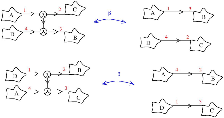
The image presents two pairs of diagrams illustrating state transitions or flow between four entities labeled A, B, C, and D. Each pair shows an initial state on the left and a transformed state on the right, connected by a bidirectional arrow labeled "β". The transitions are numerically labeled from 1 to 4. The diagrams utilize a node-and-arrow structure to represent the flow.
### Components/Axes
The diagrams consist of:
* **Nodes:** Represented by pentagonal shapes labeled A, B, C, and D.
* **Arrows:** Indicate the direction of flow or transition.
* **Numerical Labels:** Numbers 1 through 4 along the arrows, denoting the order or identifier of the transition.
* **Bidirectional Arrow:** Labeled "β", indicating a transformation or relationship between the two diagrams in each pair.
* **Circular Node:** A circle with a branching arrow, representing a decision or split point in the flow.
### Detailed Analysis or Content Details
**Diagram Pair 1 (Top)**
* **Left Diagram:**
* A connects to a circular node via arrow labeled '1'.
* D connects to the same circular node via arrow labeled '4'.
* The circular node splits into two arrows: one to C labeled '2', and one to B labeled '3'.
* **Right Diagram:**
* A connects to B via arrow labeled '3'.
* D connects to C via arrow labeled '2'.
* A connects to B via arrow labeled '3'.
* D connects to C via arrow labeled '4'.
**Diagram Pair 2 (Bottom)**
* **Left Diagram:**
* D connects to a circular node via arrow labeled '1'.
* A connects to the same circular node via arrow labeled '4'.
* The circular node splits into two arrows: one to B labeled '2', and one to C labeled '3'.
* **Right Diagram:**
* A connects to B via arrow labeled '2'.
* D connects to C via arrow labeled '3'.
* A connects to B via arrow labeled '4'.
* D connects to C via arrow labeled '1'.
### Key Observations
* The diagrams demonstrate a rearrangement of connections between the entities A, B, C, and D.
* The "β" arrow suggests a transformation or equivalence between the initial and transformed states.
* The numerical labels on the arrows appear to be consistently reassigned between the left and right diagrams within each pair.
* The circular node acts as a branching point, distributing flow to multiple entities.
### Interpretation
The diagrams likely represent a reversible transformation or a duality in the relationships between the entities A, B, C, and D. The "β" arrow indicates that the two diagrams are equivalent under some operation. The numerical labels on the arrows suggest a mapping or permutation of connections. The circular node could represent a decision point or a common intermediate state.
The transformation appears to involve swapping the connections between A/D and B/C. In the first pair, A and D initially connect to a branching point that leads to C and B. After the transformation (β), A connects directly to B, and D connects directly to C. The second pair shows a similar transformation, but with the initial connections reversed. This suggests a symmetry or duality in the system.
The diagrams could be illustrating a concept from graph theory, network analysis, or a similar field where relationships between entities are important. Without further context, it's difficult to determine the specific meaning of the transformation "β" or the significance of the numerical labels.