TECHNICAL ASSET FINGERPRINT
5b629672d534fa59925b7c1c
Click to view fullscreen
Press ESC or click to close
FOUND IN PAPERS
EXPERT: healer-alpha-free VERSION 1
RUNTIME: free/openrouter/healer-alpha
INTEL_VERIFIED
## Phase-Space Diagrams and Optical Schematic: Quantum States and Cavity System
### Overview
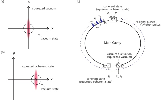
The image is a composite technical figure containing three distinct panels labeled (a), (b), and (c). Panels (a) and (b) are phase-space diagrams illustrating different quantum states of light. Panel (c) is a schematic diagram of an optical cavity system designed to generate or manipulate these states. The overall theme is quantum optics, specifically focusing on squeezed states and their application in a cavity-based system.
### Components/Axes
**Panel (a): Phase-Space Diagram - Squeezed Vacuum**
* **Axes:** Horizontal axis labeled **X** (position quadrature). Vertical axis labeled **P** (momentum quadrature). Both axes have arrows indicating positive direction.
* **Key Elements:**
* A dashed circle centered at the origin (0,0), labeled **"vacuum state"**. This represents the uncertainty of the vacuum state, which is symmetric in X and P.
* A vertically elongated, red-shaded ellipse centered at the origin, labeled **"squeezed vacuum"**. This represents a state where uncertainty in the P quadrature is reduced ("squeezed") below the vacuum level, at the expense of increased uncertainty in the X quadrature, as per the Heisenberg uncertainty principle.
**Panel (b): Phase-Space Diagram - Squeezed Coherent State**
* **Axes:** Same as panel (a): **X** (horizontal) and **P** (vertical).
* **Key Elements:**
* The same dashed circle labeled **"vacuum state"** at the origin.
* A vertically elongated, red-shaded ellipse labeled **"squeezed coherent state"**. Unlike in (a), this ellipse is displaced from the origin. Its center is located at a positive X and positive P value (approximately in the first quadrant). This indicates the state has both squeezing (reduced noise in P) and a non-zero amplitude (coherent displacement).
**Panel (c): Optical Schematic - Main Cavity System**
* **Layout:** A large, central oval loop labeled **"Main Cavity"**. Components are placed along this loop.
* **Components & Labels (Clockwise from top):**
1. **Top (Input):** A box labeled **"PSA"** (likely Phase-Sensitive Amplifier). Two inputs feed into it:
* An arrow labeled **"P"** pointing down into the PSA.
* A label **"coherent state (squeezed coherent state)"** with an arrow pointing to the PSA input.
2. **Top-Right (Output):** An arrow exits the cavity loop, labeled **"N signal pulses + N error pulses"**.
3. **Right Side:** The cavity loop continues downward.
4. **Bottom (Measurement/Output):** Two beam splitters, both labeled **"BS"**.
* The first BS has an input from below labeled **"f̂_i"** (f-hat subscript i).
* The output of the first BS goes to the second BS.
* The second BS has two outputs pointing downward:
* One labeled **"x̂_j, ê_j"** (x-hat subscript j, e-hat subscript j).
* Another labeled **"ê_j"** (e-hat subscript j).
* A label **"vacuum fluctuation (squeezed vacuum)"** with a dashed arrow points into the cavity between the two BS components.
5. **Left Side:** The cavity loop continues upward.
6. **Top-Left (Input):** A series of blue, wedge-shaped pulses entering the cavity. They are labeled:
* **"X_1"**, **"X_N"** (X subscript 1, X subscript N).
* **"e_1"**, **"e_N"** (e subscript 1, e subscript N).
* A collective label **"x_1, x_N"** and **"e_1, e_N"** points to this group of pulses.
### Detailed Analysis
* **Panel (a) Trend:** The "squeezed vacuum" state shows noise reduction (squeezing) exclusively along the P-axis. The uncertainty ellipse is symmetric about the P-axis but asymmetric relative to the X-axis.
* **Panel (b) Trend:** The "squeezed coherent state" maintains the same squeezing orientation (vertical elongation) as in (a) but is displaced to a non-zero amplitude in phase space. This combines the properties of a coherent state (displacement) and a squeezed state (reduced noise in one quadrature).
* **Panel (c) Flow & Relationships:** The schematic depicts a cyclic optical system.
* **Inputs:** The system is driven by a "coherent state (squeezed coherent state)" and a series of signal (`X_i`) and error (`e_i`) pulses at the top-left.
* **Process:** These inputs interact within the "Main Cavity". The "PSA" at the top suggests phase-sensitive amplification is a key process. "Vacuum fluctuation (squeezed vacuum)" is injected at the bottom, indicating the use of squeezed light to reduce noise.
* **Outputs:** The system produces "N signal pulses + N error pulses" at the top-right. It also has a measurement output at the bottom via beam splitters (BS), yielding quadrature (`x̂_j`) and error (`ê_j`) measurements.
* **Spatial Grounding:** The PSA is at the top center. The input pulses (`X_i`, `e_i`) enter from the upper left. The main measurement outputs are at the bottom center. The primary system output is at the upper right.
### Key Observations
1. **State Progression:** Panel (a) shows a pure squeezed state (squeezed vacuum). Panel (b) shows a more general and useful state (squeezed coherent state) that carries information (displacement) while having reduced noise.
2. **System Purpose:** The cavity system in (c) appears designed for quantum information processing or precision measurement. It uses squeezed light ("squeezed vacuum") to suppress noise and processes multiple signal (`X`) and error (`e`) modes simultaneously (`1` to `N`).
3. **Measurement Scheme:** The bottom beam splitter setup is a standard homodyne or heterodyne detection configuration for measuring the quadratures (`x̂`) and error signals (`ê`) of the output field.
4. **Closed Loop:** The diagram suggests a feedback or iterative process, where outputs (signal+error pulses) may be fed back or where the cavity stores and processes information over multiple round trips.
### Interpretation
This figure illustrates core concepts in continuous-variable quantum optics and their application in a quantum system.
* **Panels (a) & (b)** visually define the "tools": squeezed states of light. Squeezing is a quantum resource that allows measurement precision beyond the standard quantum limit (the vacuum noise level) in one variable (here, P). The coherent state in (b) represents the information-carrying component.
* **Panel (c)** shows how these tools are deployed. The "Main Cavity" acts as a quantum memory or processor. Injecting "squeezed vacuum" is a known technique to reduce the impact of vacuum noise entering through open ports, thereby improving the signal-to-noise ratio for the stored or processed quantum information (`X_i`, `e_i`).
* The system likely aims to perform **quantum error correction** or **quantum sensing** with enhanced sensitivity. The multiple input pulses (`X_1...X_N`, `e_1...e_N`) suggest a multi-mode or temporal-mode encoding scheme. The "PSA" is crucial for amplifying the signal without adding the noise that a conventional amplifier would, preserving the quantum advantage provided by squeezing.
* **Notable Anomaly/Advanced Concept:** The label "coherent state (squeezed coherent state)" at the PSA input is particularly insightful. It implies that the input itself may already be a squeezed coherent state, meaning the system is designed to process and preserve this non-classical resource throughout its operation, not just use squeezing for noise reduction at a single point.
In summary, the image connects the fundamental representation of quantum states (phase space) to a practical architecture (cavity system) that leverages those states' unique properties—specifically noise reduction via squeezing—for advanced quantum technological applications.
DECODING INTELLIGENCE...