\n
## Diagram: Compute-In-Memory Architecture
### Overview
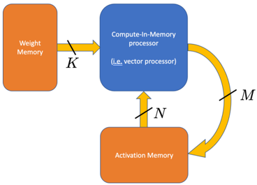
The image depicts a simplified diagram of a Compute-In-Memory (CIM) processor architecture. It illustrates the data flow between Weight Memory, the CIM processor itself, and Activation Memory. The diagram focuses on the connections and data transfer pathways rather than detailed internal components.
### Components/Axes
The diagram consists of three main rectangular blocks representing memory units and a central block representing the processor. Arrows indicate the direction of data flow, labeled with variables K, N, and M.
* **Weight Memory:** Located on the left side of the diagram, colored orange.
* **Compute-In-Memory processor:** Located in the center, colored blue. It includes the text "(i.e. vector processor)" within the block.
* **Activation Memory:** Located on the bottom of the diagram, colored orange.
* **Data Flow Arrows:**
* Arrow 1: From Weight Memory to CIM processor, labeled "K", colored yellow.
* Arrow 2: From CIM processor to Activation Memory, labeled "N", colored yellow.
* Arrow 3: From Activation Memory back to CIM processor, labeled "M", colored yellow and curved.
### Detailed Analysis or Content Details
The diagram shows a closed-loop data flow. Data labeled 'K' flows from the Weight Memory to the Compute-In-Memory processor. The processor then sends data labeled 'N' to the Activation Memory. Finally, data labeled 'M' is sent from the Activation Memory back to the Compute-In-Memory processor, completing the cycle.
The labels K, N, and M likely represent the dimensions or sizes of the data being transferred. Without further context, their specific meaning (e.g., number of bits, matrix dimensions) is unknown. The "(i.e. vector processor)" text suggests the CIM processor is a type of vector processor.
### Key Observations
The diagram highlights the tight coupling between processing and memory, which is the core principle of Compute-In-Memory architectures. The closed-loop data flow suggests an iterative process, potentially related to neural network computations or other machine learning algorithms. The diagram is highly abstract and does not provide any quantitative data.
### Interpretation
This diagram illustrates a fundamental concept in modern hardware acceleration for machine learning. Compute-In-Memory aims to overcome the von Neumann bottleneck (the separation of memory and processing) by performing computations directly within the memory array. This reduces data movement, leading to significant energy efficiency and performance gains.
The variables K, N, and M likely represent the data dimensions involved in matrix-vector multiplications, a common operation in neural networks. The iterative loop (M) suggests a repeated computation, such as forward or backward propagation in a neural network. The inclusion of "(i.e. vector processor)" indicates that the CIM processor is optimized for parallel processing of vectors, which is well-suited for matrix operations.
The simplicity of the diagram suggests it is intended as a high-level conceptual overview rather than a detailed hardware design. It emphasizes the architectural principle of integrating computation and memory, rather than specific implementation details.