## Diagram: Compute-In-Memory Processor Data Flow
### Overview
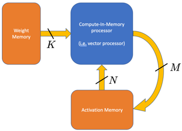
The image is a technical block diagram illustrating the data flow architecture of a Compute-In-Memory (CIM) system, specifically a vector processor. It shows the interaction between two memory units and a central processing unit, with labeled data paths indicating the width or dimensionality of the data transfers.
### Components/Axes
The diagram consists of three primary components connected by directional arrows:
1. **Weight Memory** (Left, Orange Rectangle): A memory block designated for storing model weights.
2. **Compute-In-Memory processor (i.e., vector processor)** (Top Center, Blue Rounded Rectangle): The central processing unit that performs computations directly within or near the memory structure.
3. **Activation Memory** (Bottom Center, Orange Rectangle): A memory block designated for storing activation values (intermediate outputs from neural network layers).
**Data Paths & Labels:**
* A straight, horizontal yellow arrow points from **Weight Memory** to the **Compute-In-Memory processor**. It is labeled with the letter **`K`**.
* A straight, vertical yellow arrow points from **Activation Memory** up to the **Compute-In-Memory processor**. It is labeled with the letter **`N`**.
* A curved yellow arrow points from the **Compute-In-Memory processor** back down to **Activation Memory**. It is labeled with the letter **`M`**.
### Detailed Analysis
The diagram defines a specific data movement pattern:
* **Path `K`**: Represents the transfer of weight data from dedicated weight storage into the processing unit. The label `K` likely denotes the width of this data bus or the number of weights transferred in parallel.
* **Path `N`**: Represents the transfer of activation data from activation storage into the processing unit. The label `N` likely denotes the width of this data bus or the number of activations read for computation.
* **Path `M`**: Represents the transfer of computed results (new activations) from the processing unit back to activation storage. The label `M` likely denotes the width of this data bus or the number of new activations written.
The architecture separates weight and activation memory, which is a common design in neural network accelerators to optimize data movement and compute efficiency. The "Compute-In-Memory" label suggests the processor may be physically integrated with one of the memory arrays to reduce data transfer latency and energy.
### Key Observations
* The diagram is abstract and does not provide numerical values for `K`, `N`, or `M`. These are variables representing system parameters.
* The flow is cyclical for activations: they are read (`N`), processed, and written back (`M`). Weights (`K`) are read in a feed-forward manner.
* The use of distinct colors (orange for memory, blue for processor) and shapes (rectangles vs. rounded rectangle) clearly differentiates component types.
### Interpretation
This diagram models the fundamental dataflow of a hardware accelerator for operations like matrix-vector multiplication, which is core to neural network inference and training. The separation of `K` (weight input), `N` (activation input), and `M` (activation output) paths highlights the system's parallelism and bandwidth requirements.
The architecture implies that for a given computation, `K` weights and `N` activations are fetched simultaneously to the compute unit. The result, a vector of `M` new activations, is then written back. The relative sizes of `K`, `N`, and `M` would define the parallelism and efficiency of the hardware. For example, a large `K` allows many weights to be processed at once, while a large `M` allows many results to be written per cycle. This type of diagram is used by hardware architects to plan memory bandwidth, compute array size, and overall system throughput for AI workloads.