# Technical Document Extraction: Flowchart Analysis
## Overview
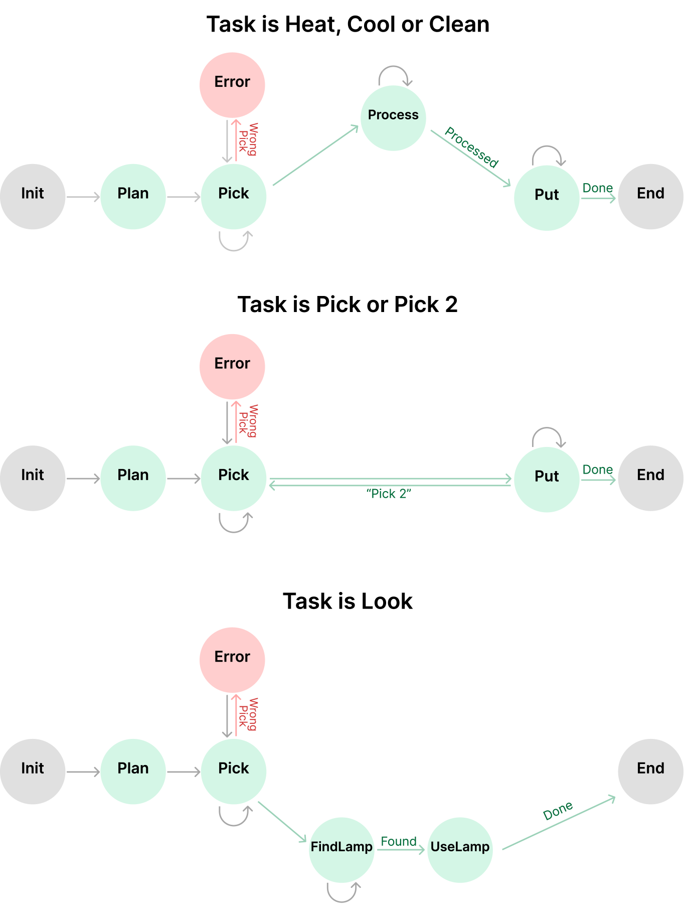
The image depicts a **flowchart** divided into three distinct sections, each representing a different task flow with error handling. The diagram uses **nodes** (circles) and **arrows** (directed edges) to represent states, actions, and transitions. Colors and labels are used to differentiate error states, task types, and process outcomes.
---
## Section 1: Task is Heat, Cool or Clean
### Nodes and Connections
1. **Init** (Gray) → **Plan** (Light Green)
- Label: None
2. **Plan** → **Pick** (Light Green)
- Label: None
3. **Pick** → **Process** (Light Green)
- Label: None
4. **Process** → **Put** (Light Green)
- Label: `Processed`
5. **Put** → **End** (Gray)
- Label: `Done`
6. **Pick** → **Error** (Pink)
- Label: `Wrong Pick`
### Key Observations
- The primary flow progresses from `Init` → `Plan` → `Pick` → `Process` → `Put` → `End`.
- An error state (`Error`) is triggered if the wrong item is picked during the `Pick` step.
---
## Section 2: Task is Pick or Pick 2
### Nodes and Connections
1. **Init** (Gray) → **Plan** (Light Green)
- Label: None
2. **Plan** → **Pick** (Light Green)
- Label: None
3. **Pick** → **Put** (Light Green)
- Label: `"Pick 2"`
4. **Put** → **End** (Gray)
- Label: `Done`
5. **Pick** → **Error** (Pink)
- Label: `Wrong Pick`
### Key Observations
- The flow skips the `Process` step compared to Section 1.
- The `Pick` step directly transitions to `Put` with a label indicating a secondary pick action (`"Pick 2"`).
- Error handling remains consistent with Section 1.
---
## Section 3: Task is Look
### Nodes and Connections
1. **Init** (Gray) → **Plan** (Light Green)
- Label: None
2. **Plan** → **Pick** (Light Green)
- Label: None
3. **Pick** → **FindLamp** (Light Green)
- Label: `Found`
4. **FindLamp** → **UseLamp** (Light Green)
- Label: None
5. **UseLamp** → **End** (Gray)
- Label: `Done`
6. **Pick** → **Error** (Pink)
- Label: `Wrong Pick`
### Key Observations
- Introduces new nodes (`FindLamp`, `UseLamp`) for a task requiring sequential actions.
- The `Found` label indicates successful identification of an object (e.g., a lamp).
- Error handling remains consistent across all sections.
---
## Common Elements Across All Sections
1. **Error Handling**
- All sections include an `Error` node connected to `Pick` with the label `Wrong Pick`.
- Error state is represented by a **pink circle**.
2. **Terminal State**
- All flows terminate at `End` (Gray node) with the label `Done`.
3. **Initialization**
- All sections start with `Init` (Gray node) → `Plan` (Light Green node).
---
## Diagram Structure
- **Color Coding**:
- **Gray**: Start/End nodes (`Init`, `End`).
- **Light Green**: Process nodes (`Plan`, `Pick`, `Process`, `Put`, `FindLamp`, `UseLamp`).
- **Pink**: Error node (`Error`).
- **Arrows**:
- Directed edges represent transitions between states.
- Labels on arrows describe the action or outcome of the transition.
---
## Summary
The flowchart illustrates three task flows with shared error handling but distinct workflows:
1. **Heat/Clean**: Involves processing after picking.
2. **Pick/Pick 2**: Skips processing, includes a secondary pick action.
3. **Look**: Requires finding and using an object.
All flows emphasize error detection at the `Pick` step and conclude with a `Done` status upon successful completion.