## Diagram: Bipartite Network Structure with Central Nodes
### Overview
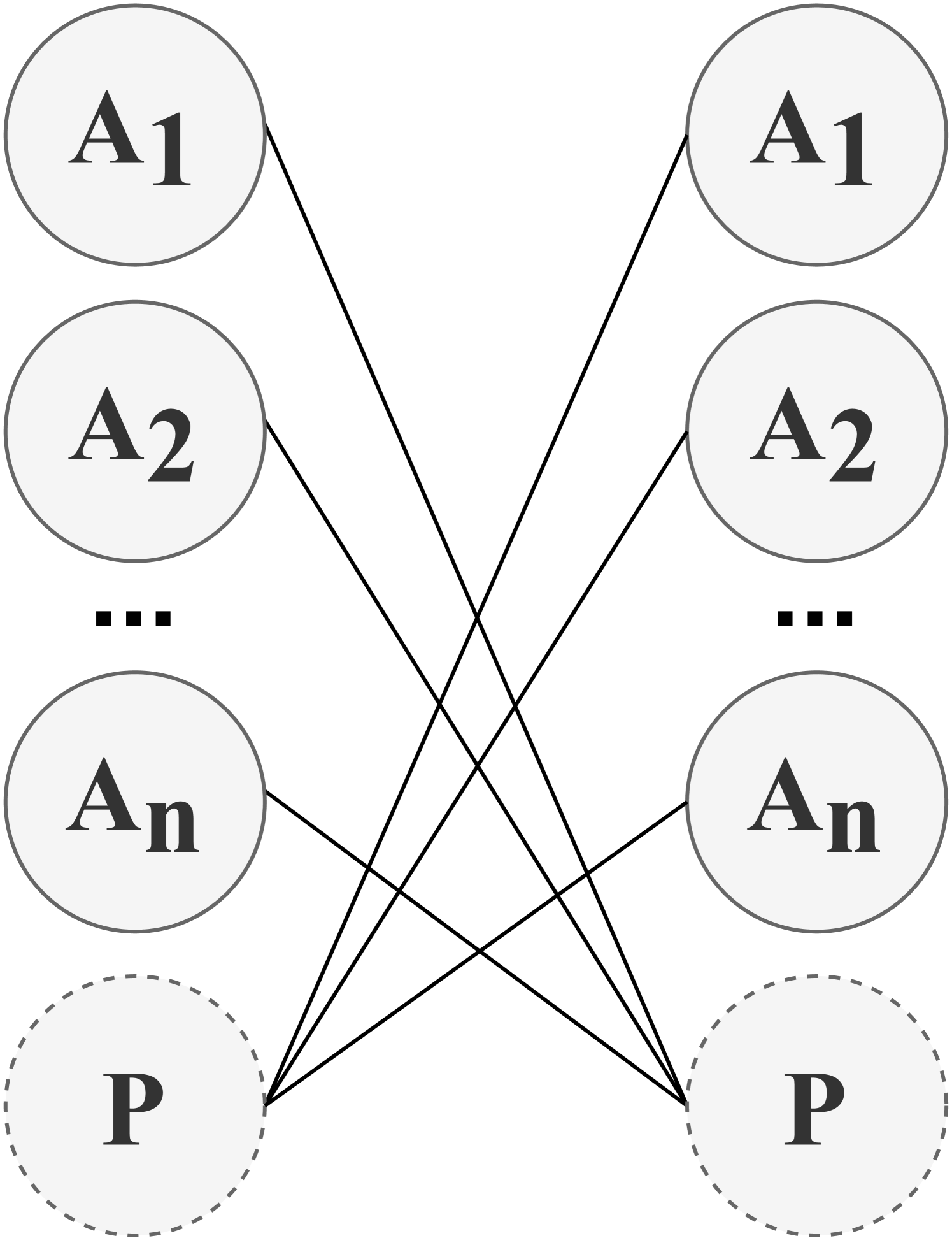
The diagram depicts a symmetrical bipartite network structure with two central nodes labeled **P** (dashed circles) connected to two mirrored columns of nodes labeled **A1**, **A2**, ..., **An** (solid circles). Lines interconnect the nodes, forming a crisscross pattern between the columns and converging at the central **P** nodes.
---
### Components/Axes
1. **Nodes**:
- **Left Column**: Labeled **A1**, **A2**, ..., **An** (solid circles).
- **Right Column**: Mirrored labels **A1**, **A2**, ..., **An** (solid circles).
- **Central Nodes**: Two **P** nodes (dashed circles) at the bottom, one connected to the left column and the other to the right column.
2. **Connections**:
- Each **A** node in the left column connects to the left **P** node via solid lines.
- Each **A** node in the right column connects to the right **P** node via solid lines.
- Lines between the two **P** nodes cross through the center, creating an "X" shape.
3. **Visual Cues**:
- Dashed borders around **P** nodes distinguish them from **A** nodes.
- Symmetry in labeling and connections suggests equivalence between left/right columns.
---
### Detailed Analysis
- **Node Labels**:
- **A1**, **A2**, ..., **An** (left and right columns) imply a sequence of entities (e.g., agents, processes, or variables).
- **P** nodes are singular and centrally positioned, suggesting they are focal points (e.g., outputs, targets, or hubs).
- **Connections**:
- All **A** nodes in a column are directly linked to their respective **P** node, indicating a one-to-many relationship.
- The crossing lines between **P** nodes imply indirect interaction or dependency between the two central nodes via the **A** nodes.
- **Dashed Borders**:
- The dashed **P** nodes may represent boundary conditions, external systems, or abstract concepts (e.g., "public" vs. "private" nodes).
---
### Key Observations
1. **Symmetry**: The left and right columns are identical in structure, suggesting mirrored roles or identical subsystems.
2. **Central Hubs**: The **P** nodes act as aggregators or mediators, receiving input from all **A** nodes in their respective columns.
3. **Cross-Connections**: The intersecting lines between **P** nodes hint at systemic interdependence or feedback loops.
---
### Interpretation
This diagram likely represents a **bipartite graph** or **network topology** where:
- **A nodes** are peripheral entities (e.g., sensors, users, or resources).
- **P nodes** are central hubs (e.g., servers, decision-makers, or systems) that process or distribute information.
- The crossing lines between **P** nodes suggest that the two hubs interact indirectly through the **A** nodes, possibly modeling a distributed system with shared dependencies.
The absence of numerical values or explicit directionality implies this is a conceptual model rather than a data-driven visualization. The dashed **P** nodes could denote special properties (e.g., "primary" vs. "secondary" roles) or external interfaces in a larger system.