## Diagram: Spatial Audio Processing
### Overview
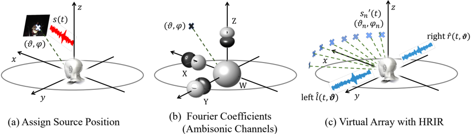
The image illustrates three stages in spatial audio processing: assigning a source position, calculating Fourier coefficients (Ambisonic channels), and creating a virtual array with Head-Related Impulse Responses (HRIR). Each stage is represented as a 3D coordinate system with a head model at the origin.
### Components/Axes
* **Coordinate Axes:** Each diagram has x, y, and z axes.
* **Head Model:** A generic head model is positioned at the origin of each coordinate system.
* **Source Position (a):**
* Image of a person with a cross indicating the source location.
* `s(t)`: Represents the audio signal.
* `(θ, φ)`: Spherical coordinates indicating the source's direction.
* **Fourier Coefficients (b):**
* `W`: A large sphere at the origin.
* `X`, `Y`, `Z`: Smaller spheres positioned along the respective axes, some shaded differently.
* `(θ, φ)`: Spherical coordinates indicating the source's direction.
* **Virtual Array (c):**
* `s_n'(t) (θ_n, φ_n)`: Represents the processed audio signal and its direction.
* Array of crosses indicating virtual speaker positions.
* `left l^(t, θ)`: Represents the processed audio signal for the left ear.
* `right r^(t, θ)`: Represents the processed audio signal for the right ear.
### Detailed Analysis
**Diagram (a): Assign Source Position**
* A 3D coordinate system with x, y, and z axes.
* A head model is located at the origin.
* An image of a person is positioned in the first quadrant (positive x, y, and z). A cross is placed on the image, indicating the sound source location.
* A waveform `s(t)` is shown near the image, representing the audio signal.
* A dashed line connects the sound source location to the origin, labeled with spherical coordinates `(θ, φ)`.
**Diagram (b): Fourier Coefficients (Ambisonic Channels)**
* A 3D coordinate system with x, y, and z axes.
* A head model is located at the origin.
* A large sphere labeled `W` is positioned at the origin.
* Smaller spheres are positioned along the x, y, and z axes, labeled `X`, `Y`, and `Z` respectively. Some spheres are shaded differently, possibly indicating phase or polarity.
* A dashed line connects a point in space to the origin, labeled with spherical coordinates `(θ, φ)`.
**Diagram (c): Virtual Array with HRIR**
* A 3D coordinate system with x, y, and z axes.
* A head model is located at the origin.
* An array of crosses is positioned in a semi-circular arc around the head, representing virtual speaker positions. Each cross is associated with a processed audio signal `s_n'(t)` and its direction `(θ_n, φ_n)`.
* Waveforms labeled `left l^(t, θ)` and `right r^(t, θ)` are shown near the left and right sides of the head, representing the processed audio signals for each ear.
### Key Observations
* The diagrams illustrate the process of spatializing audio by assigning a source position, decomposing the sound field into Fourier coefficients (Ambisonic channels), and then rendering the sound using a virtual speaker array and HRIRs.
* The spherical coordinates `(θ, φ)` are used to represent the direction of the sound source in each stage.
* The waveforms `s(t)`, `s_n'(t)`, `left l^(t, θ)`, and `right r^(t, θ)` represent the audio signal at different stages of processing.
### Interpretation
The image provides a high-level overview of spatial audio processing. It demonstrates how a sound source's position is first defined, then transformed into a set of Ambisonic coefficients, and finally rendered using a virtual speaker array and HRIRs to create a realistic spatial audio experience for the listener. The use of HRIRs allows the system to simulate how sound is perceived by the human ears, taking into account the shape of the head and ears. The virtual array simulates multiple speakers around the listener, enhancing the spatial effect.