## Diagram: Spatial Audio Processing Components
### Overview
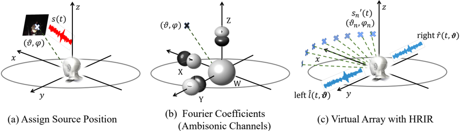
The image presents three interconnected diagrams illustrating spatial audio processing concepts: source positioning, ambisonic channel representation, and virtual array implementation with Head-Related Impulse Responses (HRIR). Each diagram uses 3D coordinate systems and vector representations to model acoustic phenomena.
### Components/Axes
**Diagram (a): Assign Source Position**
- 3D coordinate system (x, y, z axes)
- Spherical coordinate markers (θ, φ) for source direction
- Waveform label: s(t) (red waveform)
- Human head silhouette facing positive z-axis
**Diagram (b): Fourier Coefficients (Ambisonic Channels)**
- Central sphere (W) representing first-order ambisonics
- Four directional spheres (X, Y, Z, W) with vectors
- Spherical coordinate markers (θ, φ) for each channel
- Cross mark (×) indicating reference point
**Diagram (c): Virtual Array with HRIR**
- 3D coordinate system (x, y, z axes)
- Multiple blue crosses (×) labeled (θ_n, φ_n) representing virtual sources
- Waveforms: s'_n(t) (blue) and h(t, θ) (blue)
- Human head silhouette with left/right channel labels
- Legend: Blue = Virtual Array Elements
### Detailed Analysis
**Diagram (a)**
- Source position defined by spherical coordinates (θ, φ) in 3D space
- Waveform s(t) originates from source position
- Human head orientation aligned with z-axis (frontal view)
**Diagram (b)**
- Ambisonic channels represented by four spheres:
- X: Rightward vector
- Y: Forward vector
- Z: Upward vector
- W: Central omnidirectional channel
- Vectors show directional sensitivity of each channel
- Spherical coordinates (θ, φ) define angular relationships
**Diagram (c)**
- Virtual array implementation with N virtual sources (N ≥ 3)
- Each virtual source has:
- Directional coordinates (θ_n, φ_n)
- Associated HRIR waveform h(t, θ)
- Modified source waveform s'_n(t)
- Left/right channel representation with directional waveforms
### Key Observations
1. Spatial coordinate systems consistently use right-handed 3D axes
2. Ambisonic channels (X,Y,Z,W) form orthogonal basis for first-order ambisonics
3. Virtual array elements (blue crosses) are distributed around the head's coordinate system
4. HRIR waveforms (h(t, θ)) show directional filtering characteristics
5. Waveform transformations (s(t) → s'_n(t)) indicate spatial processing
### Interpretation
This diagram set demonstrates the mathematical and physical foundations of spatial audio processing:
1. **Source Localization**: Diagram (a) shows how sound sources are positioned in 3D space using spherical coordinates
2. **Ambisonic Encoding**: Diagram (b) illustrates the four-channel ambisonic representation, where each channel captures sound from a specific direction
3. **Virtual Source Synthesis**: Diagram (c) demonstrates how HRIR-based virtual arrays can create spatially localized sound sources through directional filtering
The progression from source positioning to ambisonic encoding to virtual array implementation reveals the complete pipeline for creating spatially accurate audio experiences. The use of consistent coordinate systems across diagrams emphasizes the mathematical relationships between physical space and acoustic representation.