\n
## Diagram: Informal vs. Formal Proof of Infinite Primes
### Overview
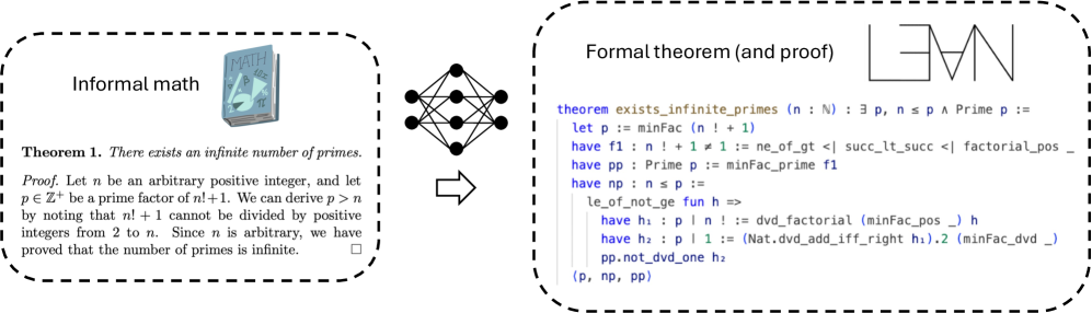
The image presents a visual comparison between an informal mathematical proof and its formal representation. The left side depicts an informal approach with a textbook and a simplified proof, while the right side shows a formal theorem and proof using symbolic logic. A diagram of a network of nodes with connections is positioned between the two sides, suggesting a transformation or mapping between the informal and formal representations.
### Components/Axes
The image is divided into three main sections:
1. **Informal Math:** Contains a textbook image, a theorem statement, and a natural language proof.
2. **Network Diagram:** A visual representation of interconnected nodes.
3. **Formal Theorem (and proof):** Contains a theorem statement in symbolic logic and a formal proof consisting of a series of logical statements.
The informal section is enclosed in a dashed-line rectangle labeled "Informal math". The formal section is enclosed in a dashed-line rectangle labeled "Formal theorem (and proof)".
### Content Details
**Informal Math Section:**
* **Textbook Image:** A book with the title "MATH" and the symbol π (pi) visible on its cover.
* **Theorem 1:** "There exists an infinite number of primes."
* **Proof:** "Let n be an arbitrary positive integer, and let p ∈ Z⁺ be a prime factor of n+1. We can derive p > n by noting that n+1 cannot be divided by positive integers from 2 to n. Since n is arbitrary, we have proved that the number of primes is infinite."
**Network Diagram:**
* A network of approximately 20 nodes connected by lines. The nodes are arranged in a roughly rectangular shape. The connections appear to be mostly between adjacent nodes, with some diagonal connections.
**Formal Theorem (and proof) Section:**
* **Theorem:** `theorem exists_infinite_primes (n : Nat) : ∃ p, n ≤ p ∧ Prime p :=`
* **Proof Steps:**
* `let p := minfac (n + 1)`
* `have f1 : n + 1 ≠ 1 := ne_of_gt (succ_lt_succ factorial_pos)`
* `have pp : Prime p := minfac_prime f1`
* `have np : n ≤ p :=`
* `le_of_not_ge fun h =>`
* `have h : p | n ! := dvd_factorial (minfac_pos h) h`
* `have h : p | 1 := (Nat.dvd_add_iff_right h).2 (minfac_dvd _)`
* `pp.not_dvd_one h2`
* `(p, np, pp)`
### Key Observations
* The diagram visually represents a transition from an intuitive, human-readable proof to a formal, machine-verifiable proof.
* The network diagram could represent the logical dependencies or relationships within the proof.
* The formal proof uses a symbolic notation common in theorem provers and formal verification systems.
* The informal proof relies on natural language and intuitive reasoning, while the formal proof relies on precise definitions and logical inference rules.
### Interpretation
The image illustrates the process of formalizing a mathematical proof. The informal proof provides a human-understandable explanation of why there are infinitely many primes. The formal proof translates this reasoning into a precise, unambiguous representation that can be checked by a computer. The network diagram likely represents the logical structure of the proof, showing how different statements and assumptions are connected. This highlights the difference between mathematical reasoning as practiced by humans and the rigorous, symbolic approach required for automated verification. The image suggests that formalization involves mapping intuitive concepts to precise logical statements and establishing a clear chain of inference. The use of a theorem prover is implied by the formal notation.