\n
## Diagram: Control Systems and Higher-order Logic Relationship
### Overview
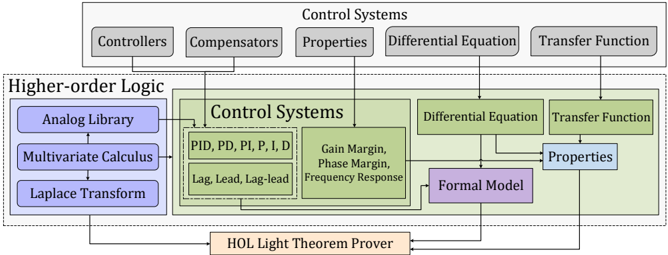
The image is a diagram illustrating the relationship between Control Systems and Higher-order Logic. It depicts a flow of information and dependencies between various components within these two domains, culminating in a formal verification process using the HOL Light Theorem Prover. The diagram is structured with a header representing Control Systems, a central block representing the core of Control Systems, and a left-side block representing Higher-order Logic. Arrows indicate the flow of information and dependencies.
### Components/Axes
The diagram consists of the following components:
* **Header (Gray):** "Control Systems" with sub-components: "Controllers", "Compensators", "Properties", "Differential Equation", "Transfer Function".
* **Higher-order Logic (Light Blue):** "Higher-order Logic" with sub-components: "Analog Library", "Multivariate Calculus", "Laplace Transform".
* **Central Control Systems Block (Light Green):** "Control Systems" with sub-components: "PID, PD, PI, P, I, D", "Lag, Lead, Lag-lead", "Gain Margin, Phase Margin, Frequency Response".
* **Formal Model (Purple):** "Formal Model".
* **HOL Light Theorem Prover (Dark Green):** "HOL Light Theorem Prover".
Arrows connect these components, indicating dependencies and information flow.
### Detailed Analysis or Content Details
The diagram shows the following connections:
1. **Header to Central Block:**
* "Controllers" connects to "PID, PD, PI, P, I, D".
* "Compensators" connects to "Lag, Lead, Lag-lead".
* "Properties" connects to "Gain Margin, Phase Margin, Frequency Response" and "Properties" (in the lower right).
* "Differential Equation" connects to "Differential Equation" (in the lower right).
* "Transfer Function" connects to "Transfer Function" (in the lower right).
2. **Higher-order Logic to Central Block:**
* "Analog Library" connects to "PID, PD, PI, P, I, D".
* "Multivariate Calculus" connects to "Gain Margin, Phase Margin, Frequency Response".
* "Laplace Transform" connects to "Transfer Function".
3. **Central Block to Formal Model:**
* "PID, PD, PI, P, I, D" connects to "Formal Model".
* "Gain Margin, Phase Margin, Frequency Response" connects to "Formal Model".
* "Differential Equation" connects to "Formal Model".
* "Transfer Function" connects to "Formal Model".
* "Properties" connects to "Formal Model".
4. **Formal Model to HOL Light Theorem Prover:**
* "Formal Model" connects to "HOL Light Theorem Prover".
5. **Higher-order Logic to HOL Light Theorem Prover:**
* "Analog Library" connects to "HOL Light Theorem Prover".
* "Multivariate Calculus" connects to "HOL Light Theorem Prover".
* "Laplace Transform" connects to "HOL Light Theorem Prover".
### Key Observations
The diagram highlights the integration of mathematical and analytical tools (Higher-order Logic) with practical control system design elements. The "Formal Model" acts as a bridge between the Control Systems components and the rigorous verification provided by the "HOL Light Theorem Prover". The diagram suggests a workflow where control system properties and designs are formally modeled and then verified for correctness and robustness.
### Interpretation
This diagram illustrates a methodology for formally verifying control systems. It demonstrates how concepts from higher-order logic, such as analog libraries, multivariate calculus, and Laplace transforms, are used to create a formal model of the control system. This formal model, encompassing elements like PID controllers, transfer functions, and properties like gain and phase margins, is then subjected to rigorous verification using the HOL Light Theorem Prover.
The diagram suggests a shift towards more reliable and trustworthy control systems by employing formal methods. The use of the HOL Light Theorem Prover implies a desire for mathematical proof of correctness, rather than relying solely on simulation and testing. This approach is particularly valuable in safety-critical applications where failures can have severe consequences. The diagram emphasizes the importance of a solid mathematical foundation for control system design and implementation. The connections between the higher-order logic components and the control system components suggest that the mathematical tools are used to analyze and model the behavior of the control system.