## Diagram: Control Systems Architecture with Higher-Order Logic Integration
### Overview
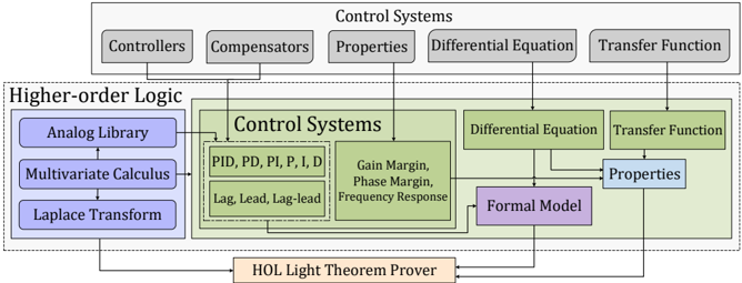
This diagram illustrates the hierarchical structure of a control systems framework, integrating mathematical foundations (Higher-Order Logic) with control theory components. It emphasizes the flow of information and dependencies between subsystems, formal models, and verification tools.
### Components/Axes
#### Top Section: Control Systems
- **Controllers**
- **Compensators**
- **Properties**
- **Differential Equation**
- **Transfer Function**
#### Left Section: Higher-Order Logic
- **Analog Library**
- **Multivariate Calculus**
- **Laplace Transform**
- **PID, PD, PI, P, I, D** (Proportional-Integral-Derivative controllers)
- **Lag, Lead, Lag-lead** (Compensation techniques)
#### Middle Section: Control Systems Subcomponents
- **Gain Margin**
- **Phase Margin**
- **Frequency Response**
#### Right Section: Formal Verification
- **Formal Model**
- **HOL Light Theorem Prover**
#### Arrows and Connections
- **Higher-Order Logic** → **Control Systems** (via arrows)
- **Control Systems** → **Differential Equation** and **Transfer Function**
- **Differential Equation** and **Transfer Function** → **Properties**
- **Properties** → **Formal Model**
- **Formal Model** → **HOL Light Theorem Prover**
### Detailed Analysis
- **Higher-Order Logic** (blue section): Contains foundational mathematical tools (e.g., Laplace Transform, Multivariate Calculus) and control strategies (PID, Lag-lead). These are prerequisites for designing control systems.
- **Control Systems** (green section): Includes core components like Controllers, Compensators, and properties (Gain Margin, Phase Margin). These are linked to mathematical models (Differential Equation, Transfer Function).
- **Properties** (lighter green): Represents system characteristics derived from differential equations and transfer functions.
- **Formal Model** (purple): Acts as an intermediate layer between control systems properties and the verification tool.
- **HOL Light Theorem Prover** (orange): A formal verification tool that validates the correctness of the formal model.
### Key Observations
1. **Hierarchical Flow**: The diagram shows a top-down flow from mathematical foundations (Higher-Order Logic) to control system design, then to formal verification.
2. **Interconnectedness**: Properties (e.g., Gain Margin) are central, linking differential equations, transfer functions, and formal models.
3. **Verification Focus**: The HOL Light Theorem Prover is positioned at the bottom, suggesting its role in ensuring the correctness of the entire system.
### Interpretation
This diagram highlights the integration of mathematical rigor (Higher-Order Logic) with practical control system design. The flow from foundational tools to formal verification underscores the importance of **formal methods** in ensuring system stability and correctness. The emphasis on properties like Gain Margin and Phase Margin indicates a focus on **robustness** and **stability analysis**. The use of the HOL Light Theorem Prover suggests a commitment to **mathematical proof-based validation**, which is critical in safety-critical systems.
**Note**: No numerical data or trends are present in the diagram; it is a conceptual representation of system architecture and dependencies.