## System Architecture Diagram: Edge Device to Multi-Board System
### Overview
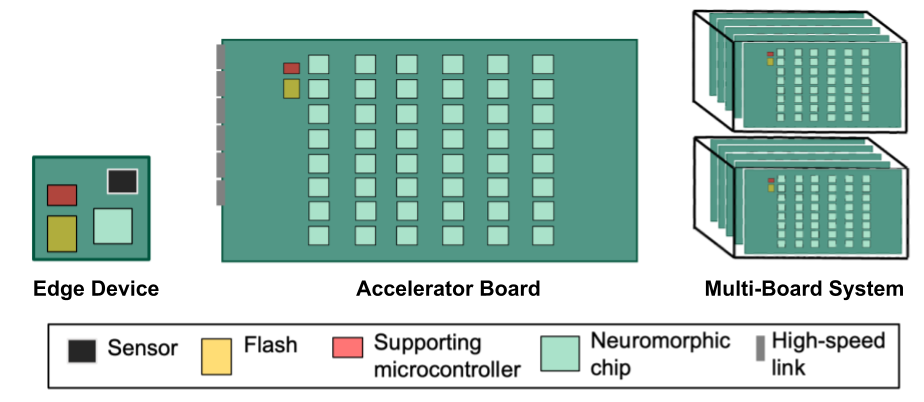
The image presents a system architecture diagram illustrating the progression from an edge device to a multi-board system. It showcases the components and their arrangement at each stage, including an edge device, an accelerator board, and a multi-board system. The diagram uses color-coded blocks to represent different components, with a legend provided at the bottom.
### Components/Axes
* **Titles:**
* Edge Device
* Accelerator Board
* Multi-Board System
* **Legend (located at the bottom of the image):**
* Black: Sensor
* Yellow: Flash
* Red: Supporting microcontroller
* Light Green: Neuromorphic chip
* Gray: High-speed link
### Detailed Analysis
* **Edge Device:** A square board containing four components: a black square (sensor), a yellow square (flash), a red square (supporting microcontroller), and a light green square (neuromorphic chip).
* **Accelerator Board:** A rectangular board with multiple light green squares (neuromorphic chips) arranged in a grid pattern. The grid appears to be 7 rows by 5 columns, totaling 35 chips. The top-left corner of the board also contains a red square (supporting microcontroller) and a yellow square (flash). The left edge of the board has 5 gray rectangles (high-speed links).
* **Multi-Board System:** Two stacked boxes, each containing multiple accelerator boards. Each accelerator board within the boxes has the same layout as the single accelerator board, including the grid of light green squares (neuromorphic chips), the red square (supporting microcontroller), the yellow square (flash), and the gray rectangles (high-speed links).
### Key Observations
* The diagram illustrates a scaling of computational resources from a single edge device to a system with multiple accelerator boards.
* The accelerator board utilizes a grid of neuromorphic chips, suggesting parallel processing capabilities.
* The presence of high-speed links indicates inter-board communication within the multi-board system.
* The edge device contains all component types, while the accelerator board primarily features neuromorphic chips.
### Interpretation
The diagram depicts a hierarchical system architecture designed for computationally intensive tasks. The edge device likely performs initial data acquisition and preprocessing, while the accelerator board provides significant computational power through its array of neuromorphic chips. The multi-board system further scales the computational capacity by combining multiple accelerator boards, enabling the processing of even larger datasets or more complex algorithms. The high-speed links facilitate communication and data transfer between the boards, ensuring efficient operation of the system. The presence of a supporting microcontroller on both the edge device and accelerator board suggests control and management functionalities at each level.