## Diagram: Hardware Scalability Hierarchy (Edge to Multi-Board System)
### Overview
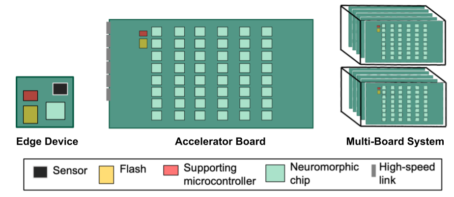
The image illustrates a hierarchical hardware architecture for neuromorphic computing, demonstrating how components scale from a single, standalone edge device to a high-density, multi-board computing system. The diagram uses a color-coded legend to identify specific hardware components across three levels of integration.
### Components/Axes
The diagram utilizes a legend at the bottom to define the hardware components:
* **Black Square:** Sensor
* **Yellow Square:** Flash
* **Red Square:** Supporting microcontroller
* **Light Green Square:** Neuromorphic chip
* **Grey Rectangle:** High-speed link
### Detailed Analysis
#### 1. Edge Device (Left)
* **Description:** A single, small, square-shaped board.
* **Components:**
* 1x Sensor (Black)
* 1x Flash (Yellow)
* 1x Supporting microcontroller (Red)
* 1x Neuromorphic chip (Light Green)
* **Layout:** The components are arranged in a compact, non-grid configuration.
#### 2. Accelerator Board (Center)
* **Description:** A large, rectangular board designed for high-density processing.
* **Components:**
* **Neuromorphic Chips:** A grid of 40 chips (5 rows by 8 columns) in Light Green.
* **Control/Storage:** 1x Supporting microcontroller (Red) and 1x Flash (Yellow) located in the top-left corner of the board.
* **Connectivity:** 5x High-speed links (Grey) positioned along the left vertical edge of the board.
#### 3. Multi-Board System (Right)
* **Description:** A high-performance computing configuration consisting of two vertical stacks.
* **Structure:**
* Two stacks are visible, positioned one above the other.
* Each stack contains 4 Accelerator Boards, totaling 8 Accelerator Boards in the system.
* Each board within the stack maintains the same internal component layout as the standalone Accelerator Board described above.
### Key Observations
* **Scaling Strategy:** The architecture demonstrates a clear modular scaling path: from a single chip (Edge) to a 40-chip board (Accelerator), to a 320-chip system (Multi-Board System, assuming 8 boards x 40 chips).
* **Connectivity Requirement:** The "High-speed link" is absent on the Edge Device but present on the Accelerator Board, indicating that as the system scales, inter-board communication becomes a critical design requirement.
* **Standardization:** The "Supporting microcontroller" and "Flash" components appear to be standard control units that accompany the neuromorphic processing array at both the single-board and multi-board levels.
### Interpretation
This diagram represents a roadmap for neuromorphic hardware deployment.
* **Edge Device:** Likely intended for localized, low-power, real-time inference tasks where data is captured directly by the sensor and processed on-site.
* **Accelerator Board:** Represents a transition to high-performance computing (HPC). The grid-like arrangement of 40 neuromorphic chips suggests a massively parallel processing architecture designed for complex neural network workloads.
* **Multi-Board System:** This configuration implies a data-center or server-grade environment. By stacking multiple accelerator boards, the system achieves massive scale, likely for training large models or handling high-throughput inference tasks. The inclusion of "High-speed links" suggests that the primary engineering challenge at this scale is managing data bandwidth between the boards to prevent bottlenecks.