\n
## Diagram: System Architecture - Edge to Multi-Board
### Overview
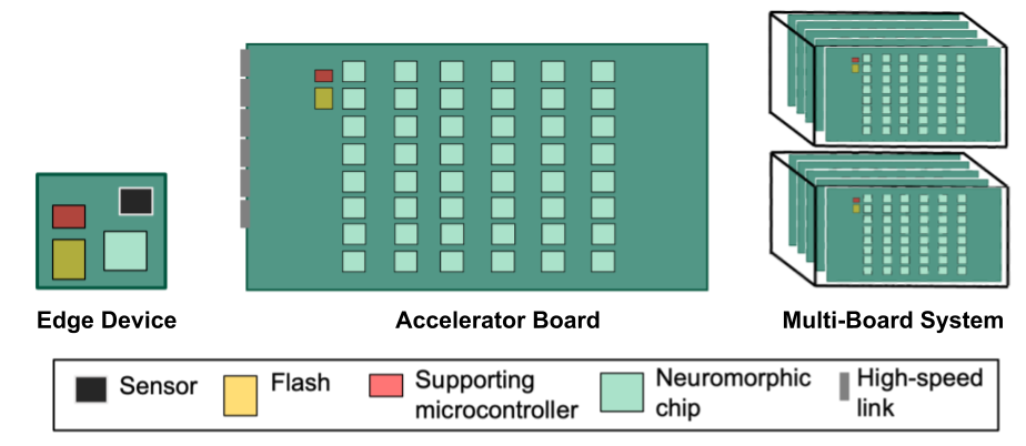
The image depicts a system architecture progressing from an "Edge Device" to an "Accelerator Board" and finally to a "Multi-Board System". The diagram illustrates the components present in each stage and their relative arrangement. It's a visual representation of a scalable computing system, likely for edge computing or AI applications.
### Components/Axes
The diagram is labeled with three main sections: "Edge Device", "Accelerator Board", and "Multi-Board System", positioned horizontally from left to right. A legend at the bottom identifies the components using color-coding:
* **Black:** Sensor
* **Yellow:** Flash
* **Red:** Supporting microcontroller
* **Light Green:** Neuromorphic chip
* **Light Blue:** High-speed link
### Detailed Analysis or Content Details
**Edge Device:**
* Contains one black square (Sensor), one yellow square (Flash), and one red square (Supporting microcontroller).
* The components are arranged in a roughly triangular configuration.
**Accelerator Board:**
* Contains one black square (Sensor), one yellow square (Flash), one red square (Supporting microcontroller), and approximately 30 light green squares (Neuromorphic chip).
* The neuromorphic chips are arranged in a grid-like pattern.
* There are several light blue lines (High-speed link) connecting various components.
**Multi-Board System:**
* Consists of a stack of approximately 5 Accelerator Boards.
* Each board within the stack has the same component arrangement as the single Accelerator Board: one black square (Sensor), one yellow square (Flash), one red square (Supporting microcontroller), and approximately 30 light green squares (Neuromorphic chip).
* Light blue lines (High-speed link) connect the boards within the stack.
### Key Observations
* The number of neuromorphic chips increases significantly as the system scales from the Accelerator Board to the Multi-Board System.
* The Edge Device has a minimal component set, suggesting it focuses on data acquisition and initial processing.
* The Accelerator Board and Multi-Board System are designed for more intensive computation, as evidenced by the large number of neuromorphic chips.
* The high-speed links suggest a focus on efficient data transfer between components and boards.
### Interpretation
The diagram illustrates a hierarchical system architecture designed for increasing computational power and scalability. The Edge Device acts as a sensor and initial processing unit. The Accelerator Board provides a significant increase in processing capability through the addition of numerous neuromorphic chips. Finally, the Multi-Board System scales the processing power further by stacking multiple Accelerator Boards. This architecture is likely intended for applications requiring real-time data processing at the edge, such as machine learning inference or computer vision. The increasing number of neuromorphic chips suggests a focus on energy-efficient and parallel processing. The high-speed links are crucial for maintaining performance as the system scales. The diagram doesn't provide specific performance metrics or power consumption data, but it clearly demonstrates a design philosophy centered around scalability and computational efficiency.