## Diagram: Neuromorphic Computing Hardware Architecture
### Overview
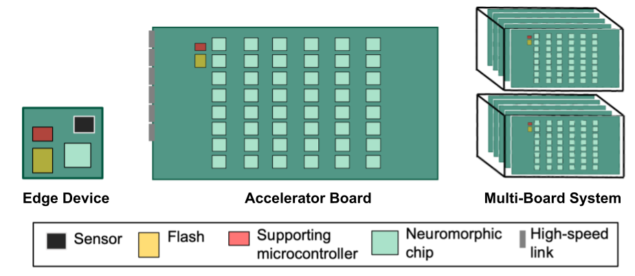
The image is a technical diagram illustrating three hierarchical levels of a neuromorphic computing system: a compact Edge Device, a scalable Accelerator Board, and a high-density Multi-Board System. It uses color-coded blocks to represent different hardware components and their arrangement across these levels.
### Components/Axes
The diagram is divided into three main visual sections, each with a text label below it:
1. **Left Section:** Labeled "Edge Device". Depicts a small, square green circuit board.
2. **Center Section:** Labeled "Accelerator Board". Depicts a larger, rectangular green circuit board.
3. **Right Section:** Labeled "Multi-Board System". Depicts two stacks of multiple Accelerator Boards.
A legend is positioned at the bottom of the entire image, defining the color-coded components:
* **Black Square:** Sensor
* **Yellow Rectangle:** Flash
* **Red Rectangle:** Supporting microcontroller
* **Light Green Square:** Neuromorphic chip
* **Gray Vertical Bar:** High-speed link
### Detailed Analysis
**1. Edge Device (Left):**
* A small, square green board.
* Contains one of each component type, arranged in a 2x2 grid:
* Top-left: Red rectangle (Supporting microcontroller)
* Top-right: Black square (Sensor)
* Bottom-left: Yellow rectangle (Flash)
* Bottom-right: Light green square (Neuromorphic chip)
**2. Accelerator Board (Center):**
* A large, rectangular green board.
* **Main Grid:** Contains a dense grid of light green squares (Neuromorphic chips). The grid is arranged in 8 columns and 10 rows, totaling 80 neuromorphic chips.
* **Top-Left Corner:** Contains a red rectangle (Supporting microcontroller) and a yellow rectangle (Flash), placed above the main grid.
* **Left Edge:** Features a gray vertical bar (High-speed link) running along the side of the board.
**3. Multi-Board System (Right):**
* Depicts two separate stacks, one above the other.
* Each stack consists of multiple (approximately 4-5 visible layers) Accelerator Boards stacked together.
* The top board of each stack is visible, showing the same layout as the central Accelerator Board: a grid of light green squares (Neuromorphic chips) with a red (Supporting microcontroller) and yellow (Flash) block in the top-left corner.
### Key Observations
* **Scalability:** The diagram clearly shows a scaling path from a single, integrated Edge Device to a board with many neuromorphic chips, and finally to a system stacking multiple such boards.
* **Component Hierarchy:** The Edge Device integrates all component types (sensor, memory, controller, compute) in a minimal form. The Accelerator Board focuses on massively parallel neuromorphic compute, supported by a single controller and flash memory. The Multi-Board System scales the compute density by stacking boards.
* **Interconnect:** The presence of a "High-speed link" on the Accelerator Board's edge implies a mechanism for communication between boards within a stack or between different stacks in the Multi-Board System.
* **Uniformity:** The neuromorphic chips are represented as identical, uniform units in a regular grid, suggesting a homogeneous architecture for parallel processing.
### Interpretation
This diagram outlines a modular and scalable hardware architecture for neuromorphic computing, which is a brain-inspired approach to computer engineering.
* **The Edge Device** represents the endpoint sensor node. It integrates sensing (Sensor), local storage (Flash), control (Supporting microcontroller), and neuromorphic processing (Neuromorphic chip) into a single unit suitable for deployment in the field. Its small size and integrated nature suggest it's designed for low-power, real-time processing at the data source.
* **The Accelerator Board** is a compute-dense module. Its primary purpose is to provide a large array of neuromorphic processors (80 chips in this depiction) for heavy computational tasks. The single supporting microcontroller and flash likely manage the board's operation and store firmware or models. The high-speed link is critical, as it enables the board to either receive data from sensors (like the Edge Device) or to connect with other boards to form a larger system.
* **The Multi-Board System** demonstrates how computational power can be scaled vertically by stacking Accelerator Boards. This is a common approach in high-performance computing to increase density without drastically increasing the physical footprint. The two separate stacks might represent independent processing clusters or a demonstration of how the system can be expanded.
**Underlying Message:** The architecture promotes a flexible ecosystem where simple, smart sensors (Edge Devices) can feed data to or be controlled by powerful, scalable neuromorphic compute clusters (Multi-Board Systems). This is well-suited for applications requiring distributed intelligence, such as robotics, autonomous systems, or large-scale sensory networks, where processing needs to happen both at the edge and in centralized, powerful accelerators.