## Diagram & Chart: Neural Network Training Accuracy
### Overview
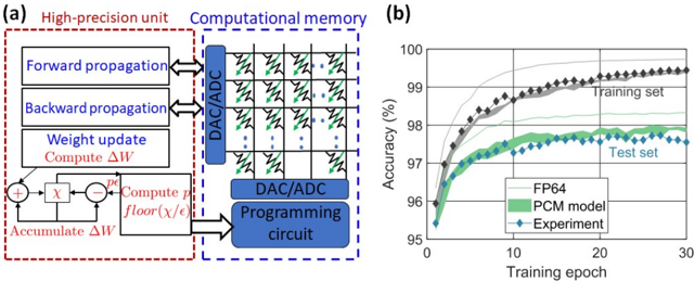
The image contains two main parts: (a) a diagram illustrating a high-precision unit and computational memory architecture for neural network training, and (b) a chart showing the accuracy of different models (FP64, PCM model, and Experiment) on training and test sets over training epochs.
### Components/Axes
**(a) Diagram:**
* **High-precision unit (red dashed box):** Contains blocks labeled "Forward propagation", "Backward propagation", "Weight update", "Compute ΔW", "Accumulate ΔW", and a computational block with "+", "x", and "floor(x/ε)".
* **Computational memory (blue dashed box):** Contains an array of memory cells with resistors and DAC/ADC connections. Also contains a "DAC/ADC Programming circuit".
* Arrows indicate data flow between the high-precision unit and the computational memory.
**(b) Chart:**
* **X-axis:** "Training epoch" ranging from 0 to 30.
* **Y-axis:** "Accuracy (%)" ranging from 95 to 100.
* **Data Series:**
* "Training set" (black diamonds)
* "Test set" (grey diamonds)
* "FP64" (light blue solid line)
* "PCM model" (green solid line)
* "Experiment" (teal solid line with blue diamonds)
* **Legend:** Located in the top-right corner, associating colors with the data series.
### Detailed Analysis or Content Details
**(a) Diagram:**
The diagram depicts a system for neural network training. The "High-precision unit" performs the standard forward and backward propagation steps, calculates weight updates (ΔW), and accumulates these updates. The "Computational memory" appears to store weights and perform computations using DAC/ADC conversion and a programming circuit. The "floor(x/ε)" block suggests a quantization operation. The arrows indicate a bidirectional flow of data between the two units.
**(b) Chart:**
* **Training Set:** Starts at approximately 96.5% accuracy at epoch 0, increases rapidly to approximately 99.2% accuracy by epoch 10, and plateaus around 99.3% for the remainder of the training period (epochs 10-30).
* **Test Set:** Starts at approximately 97.2% accuracy at epoch 0, increases to approximately 98.2% accuracy by epoch 10, and plateaus around 97.8% for the remainder of the training period.
* **FP64:** Starts at approximately 96.8% accuracy at epoch 0, increases to approximately 99.1% accuracy by epoch 10, and plateaus around 99.2% for the remainder of the training period.
* **PCM Model:** Starts at approximately 96.5% accuracy at epoch 0, increases to approximately 98.5% accuracy by epoch 10, and plateaus around 98.7% for the remainder of the training period.
* **Experiment:** Starts at approximately 96.7% accuracy at epoch 0, increases to approximately 98.8% accuracy by epoch 10, and plateaus around 98.9% for the remainder of the training period.
### Key Observations
* All models exhibit a rapid increase in accuracy during the initial training epochs (0-10).
* The training set consistently achieves higher accuracy than the test set, indicating some degree of overfitting.
* The "Experiment" model achieves the highest accuracy on both the training and test sets, followed by the "PCM model" and then "FP64".
* The accuracy plateaus for all models after approximately 10 epochs, suggesting that further training would yield minimal improvements.
### Interpretation
The diagram illustrates a novel architecture for neural network training that leverages computational memory to potentially improve efficiency or reduce precision requirements. The chart demonstrates the performance of this architecture ("Experiment") compared to traditional floating-point (FP64) and a "PCM model" (likely a phase-change memory based model).
The results suggest that the "Experiment" model achieves comparable or slightly better accuracy than FP64, while the PCM model performs well but slightly underperforms the "Experiment". The gap between training and test accuracy indicates that the models are overfitting to the training data, which could be addressed through regularization techniques. The plateau in accuracy after 10 epochs suggests that the models have converged and further training is unlikely to yield significant improvements. The use of a "floor(x/ε)" block in the diagram suggests that the system may be employing quantization to reduce memory usage or computational complexity. The DAC/ADC components indicate a conversion between digital and analog signals, potentially for efficient weight storage and computation within the computational memory.